MPCBL0010
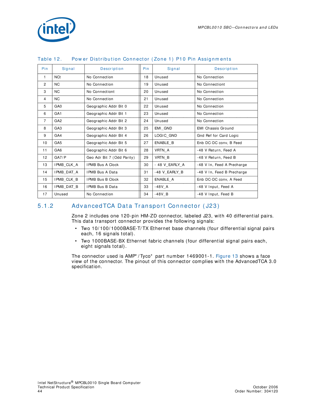
Table 12. Power Distribution Connector (Zone 1) P10 Pin Assignments
Pin | Signal | Description |
| Pin | Signal | Description |
|
|
|
|
|
|
|
1 | NCt | No Connection |
| 18 | Unused | No Connection |
|
|
|
|
|
|
|
2 | NC | No Connection |
| 19 | Unused | No Connectiont |
|
|
|
|
|
|
|
3 | NC | No Connectiont |
| 20 | Unused | No Connection |
|
|
|
|
|
|
|
4 | NC | No Connection |
| 21 | Unused | No Connection |
|
|
|
|
|
|
|
5 | GA0 | Geographic Addr Bit 0 |
| 22 | Unused | No Connection |
|
|
|
|
|
|
|
6 | GA1 | Geographic Addr Bit 1 |
| 23 | Unused | No Connection |
|
|
|
|
|
|
|
7 | GA2 | Geographic Addr Bit 2 |
| 24 | Unused | No Connection |
|
|
|
|
|
|
|
8 | GA3 | Geographic Addr Bit 3 |
| 25 | EMI_GND | EMI Chassis Ground |
|
|
|
|
|
|
|
9 | GA4 | Geographic Addr Bit 4 |
| 26 | LOGIC_GND | Gnd Ref for Card Logic |
|
|
|
|
|
|
|
10 | GA5 | Geographic Addr Bit 5 |
| 27 | ENABLE_B | Enb |
|
|
|
|
|
|
|
11 | GA6 | Geographic Addr Bit 6 |
| 28 | VRTN_A | |
|
|
|
|
|
|
|
12 | GA7/P | Geo Adr Bit 7 (Odd Parity) |
| 29 | VRTN_B | |
|
|
|
|
|
|
|
13 | IPMB_CLK_A | IPMB Bus A Clock |
| 30 | - 48 V_EARLY_A | |
|
|
|
|
|
|
|
14 | IPMB_DAT_A | IPMB Bus A Data |
| 31 | ||
|
|
|
|
|
|
|
15 | IPMB_CLK_B | IPMB Bus B Clock |
| 32 | ENABLE_A | Enb |
|
|
|
|
|
|
|
16 | IPMB_DAT_B | IPMB Bus B Data |
| 33 | ||
|
|
|
|
|
|
|
17 | Unused | No Connection |
| 34 | ||
|
|
|
|
|
|
|
5.1.2AdvancedTCA Data Transport Connector (J23)
Zone 2 includes one
•Two
•Two
The connector used is AMP*/Tyco* part number
Intel NetStructure® MPCBL0010 Single Board Computer |
|
Technical Product Specification | October 2006 |
44 | Order Number: 304120 |
