Connectors and LEDs—MPCBL0010 SBC
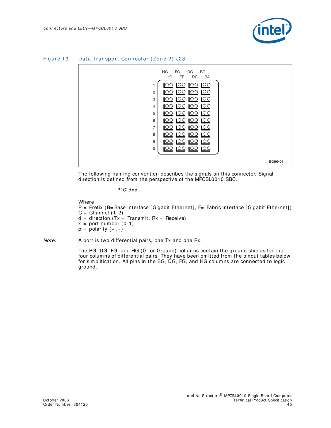
Figure 13. Data Transport Connector (Zone 2) J23
HG FG DG BG
HG FE DC BA
1
2
3
4
5
6
7
8
9
10
The following naming convention describes the signals on this connector. Signal direction is defined from the perspective of the MPCBL0010 SBC.
P[C]dxp
Where:
P = Prefix (B=Base interface [Gigabit Ethernet], F= Fabric interface [Gigabit Ethernet]) C = Channel
d = direction (Tx = Transmit, Rx = Receive)
x= port number
Note: A port is two differential pairs, one Tx and one Rx.
The BG, DG, FG, and HG (G for Ground) columns contain the ground shields for the four columns of differential pairs. They have been omitted from the pinout tables below for simplification. All pins in the BG, DG, FG, and HG columns are connected to logic ground.
| Intel NetStructure® MPCBL0010 Single Board Computer |
October 2006 | Technical Product Specification |
Order Number: 304120 | 45 |