MPCBL0010
operating system launches. If the boot sequence fails or the CPU hangs, the HDD (POST) LED will remain operational in POST code mode and repeat indefinitely the last POST code blink sequence as defined below:
1.Blink simultaneously amber and green one time: start of the sequence.
2.Blink amber
3.Blink green
4.Repeat the sequence (see step 1).
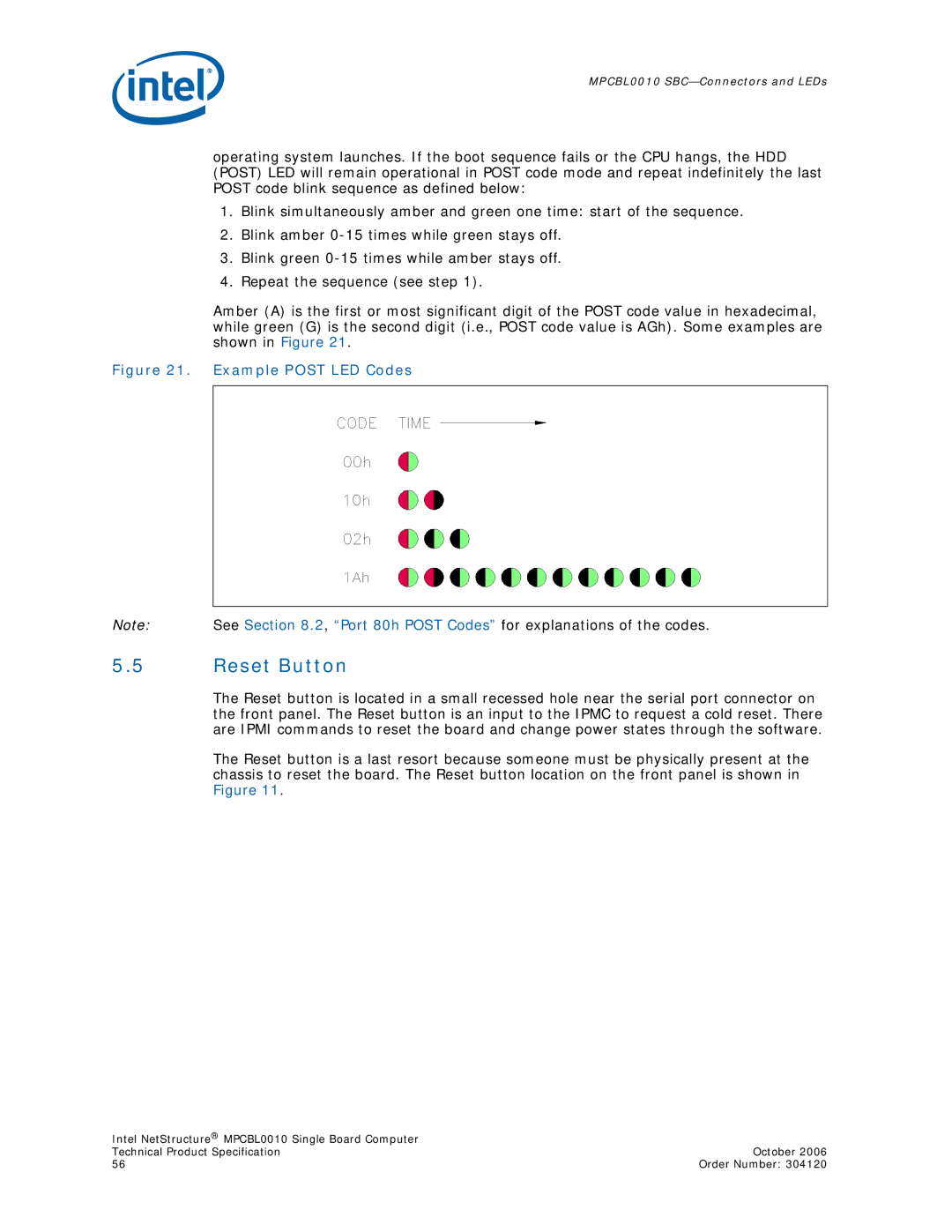
Amber (A) is the first or most significant digit of the POST code value in hexadecimal, while green (G) is the second digit (i.e., POST code value is AGh). Some examples are shown in Figure 21.
Figure 21. Example POST LED Codes
Note: See Section 8.2, “Port 80h POST Codes” for explanations of the codes.
5.5Reset Button
The Reset button is located in a small recessed hole near the serial port connector on the front panel. The Reset button is an input to the IPMC to request a cold reset. There are IPMI commands to reset the board and change power states through the software.
The Reset button is a last resort because someone must be physically present at the chassis to reset the board. The Reset button location on the front panel is shown in Figure 11.
Intel NetStructure® MPCBL0010 Single Board Computer |
|
Technical Product Specification | October 2006 |
56 | Order Number: 304120 |