Hydro Unit
AIR TO WATER HEAT PUMP
Outdoor Unit
Hot Water Cylinder
Contents
9 Method of Defect Diagnosis . . . . . . . . . . . . . . . . . . . . . . . . . . . . . . . . . . . . . . . . . . . .
About symbols
1 SAFETY PRECAUTIONS
DANGER
DANGER
•Do not disassemble or modify the parts also
• Failure to do so may cause an electric shock
2 NEW REFRIGERANT R410A
2-1.Safety During Installation and Service
2-2-1.Steel pipe and joint
2-2.Installing refrigerant pipe
Copper pipe
Table 2-1Wall thickness of copper pipe
Flare dimension
Flare and precautions
2-2-2.Processing of piping materials
Figure
Nominal diameter
Flare connecting procedure and precautions
Outer diameter mm
Tightening torque N•m kgf•m
2-3-1.Necessary tools
2-3.Tools
General tools Conventional tools are available
Fig. 2-4-1Configuration of refrigerant charging
2-4.Recharging of refrigerant
Cylinder with siphon
Low temperature brazing metal
2-5.Brazing of pipes
Why flux is necessary
Characteristics of flux
Fig Prevention of oxidation during brazing
Specifications
Unit name
4-1.Hydro unit
4 Outside Drawing
HWS-802XWHM3-E, 802XWHT6-E
HWS-1402XWHM3-E, 1402XWHT6-E, 1402XWHT9-E
HWS-802H-E
Outdoor unit
HWS-1102H-E, 1402H-E
HWS-3001CSHM3-E-UKHWS-2101CSHM3-E-UK
4-3.Hot water cylinder
HWS-1501CSHM3-E-UK
Hydro Unit
Wiring Diagram
HWS-1402XWHT9-E
HWS-802XWHT6-E
Control board
5-2.Outdoor Unit
5-3.Hot Water Cylinder Unit
6-1.Hydro Unit
Key Electric Component Rating
HWS-802XWHM3-E, 802XWHT6-E
Model name
HWS-1402XWHM3-E, 1402XWHT6-E, 1402XWHT9-E
Component name
Type name
HWS-802H-E
6-2.Outdoor Unit
HWS-1102H-E, 1402H-E
6-3.Hot Water Cylinder Unit
6-4.Water Heat Exchange Control Board
HWS-802H-E
6-5.Outdoor Control Board
HWS-1102H-E, 1402H-E
System Diagram
Diagram
System
7-1.Water
Installation example of water circuit
HWS-802XWHM3-E, 802XWHT6-E/802H-E
7-2.Refrigeration Cycle System Diagram
Refrigerant
R410A ... 1.8 kg
Item
8 Operational Description
Item
Item
Item
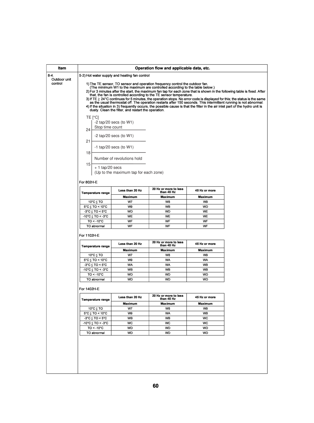
Operation flow and applicable data, etc
Item
TTW sensor
Hot water cylinder unit
2 Heating operation
3 Cooling operation
Operation
Item
Switches to Hot water
Operation flow and applicable data, etc
HOT WATER button set to ON
8 Anti bacteria ANTI BACTERIA operation
9 Night set back NIGHT SET BACK operation
11 AUTO operation
12 Nighttime low-noiseoperation
Item
Hz signal correction
Operation flow and applicable data, etc
Hydro unit
1-2High temperature release control
2 Heater control
2 Control at the time of heating heater operation
3 Circulation pump control
Flow rateL/min
Operation flow and applicable data, etc
Flow rateL/min
Operation flow and applicable data, etc
Item
8-1Pipingfreeze prevention control
8-2Piping freeze prevention control
3. Hydro Unit
Operation flow and applicable data, etc
Item
TD C
111 109 106 103 96
Item
Settings
Operation flow and applicable data, etc
Current degradation
Operation flow and applicable data, etc
Item
TL C
WE tap
Operation flow and applicable data, etc
Item
TE C 2tap/20 secs to W1 24 Stop time count
2tap/20 secs to W1 21 1tap/20 secs to W1
Outdoor fan
Compressor
4-wayvalve
Outdoor PMV 0pulse
Usual
when TO sensor fails
Operation flow and applicable data, etc
Item
Heating TC Cooling TL C
a b c d e
9 Method of Defect Diagnosis
9-1.Matters to be confirmed first
9-3.Outline of the determination diagram
Defect mode detected by the water heat exchange
9-3-4.How to diagnose by error code
Page
Page
Defect mode detected by the outdoor unit
Page
Page
Defect mode detected by the remote control
A01 Error Pump flow determination
9-4.Diagnosis flow chart for each error code
9-4-1.Hydro unit failure detection
Page
Page
A04 Error Freeze prevention control
A05 Error Piping freeze prevention control
Page
Page
Page
A11 Error Release protection operation
Page
E04 Error
F04 Error TD sensor failure
F03 Error TC sensor failure
F06 Error TE sensor failure
F08 Error TO sensor failure
F07 Error TL sensor failure
F10 Error TWI sensor failure
F14 Error TTW sensor failure
F11 Error TWO sensor failure
F17 Error TFI sensor failure
F19 Error THO sensor detach failure
F18 Error THO sensor failure
F23 Error Lo pressure sensor detach failure
F20 Error TFI detach failure
F30 Error Enhanced IC failure
F29 Error EEPROM failure
L07 Error
L09 Error
9-4-2.Outdoor Unit Failure Detection
Diagnosis procedure for each check code
Check code
Any of the following abnormality may occur
Check code
Check code
Check code
Check code
Check code
Check code
Check code
TD, TL sensors
TC, TWI, TWO, TFI, TTW, TE, TS, TO sensors
9-5-1.Operation check mode
9-5.Operation check by PC board switch
Operation check mode
9-6-1.Hydro unit
9-6.Brief method for checking the key components
9-6-2.Outdoor unit
Hydro unit 1. Hydro unit Setting
10Hydro unit and Outdoor Unit Settings
2. Hydro unit Function Code Setting
Item
Function code table
Details
First shipment
Item
Remote controller function code table
Details
Fist shipment
1, 4
1, 4 2,
3. Trial Operation
4. Auto Curve Setting
1 4
5. Time Setting
3,6,7
6. Scheduled Operation Setting
2,3 1,3
7. Frost Protection Setting
3 2,4
8. NIGHT Operation Setting
2 3 4
9. Anti Bacteria Setting
3 2,4 51
11. Nighttime Low-noiseSetting
10. Hot Water Boost Setting
13. Rated Operation Setting
12. Forced Defrosting Setting
button for temperature setting
Sensor temperature display calling
Press the TEST
and CL
3 Pressing the TEST
15. Failure History Calling Function
button returns to the normal
display
Outdoor unit 16 Outdoor Unit Setting
1 Overview
Note: All the LEDs have no color when off
For operation
For display
2 -1.Indication switching list
2 LED indication switching SW800, SW803 operation
Switch
Function and details
2 -2.Abnormality indication
Current value for the outdoor unit only is shown
<Special operation>
CN701 Between 1 to 4 Voltage = Approx.
1. Hydro Unit
11How to Exchange Main Parts
Work procedure
Electric parts assembly
Work procedure
Remarks
Relay board
Exchange parts name
Exchange parts name
Work procedure
Remarks
Remarks
Work procedure
Pump
fixing
Flow switch
Work procedure
Flow switch
Exchange parts name
Exchange parts name
Exchange parts name
2.Outdoor Unit 2-1. HWS-802H-E
Work procedure
Exchange parts
Remarks
Exchange parts
name
Compressor lead, Relay connector
Work procedure
Exchange parts
Remarks
Exchange parts
name
name
name
Exchange parts
Work procedure
Remarks
SW804
name
2-2. HWS-1102H-E, 1402H-E
Exchange parts
name
Exchange parts
name
name
name
Exchange parts
Work procedure
Remarks
Recess Pulse motor valve body
<Inspection items>
12Periodic Inspection Items
Hydro Unit
13Part Exploded View, Part List
Page
Number of pieces per unit
HWS802H-E
Outdoor Unit
Safety
Reactor Control board assembly Bushing Collar
Inverter Assembly HWS-802H-E
Sensor assembly 701 F6 TS, TE, TD sensor
707 Fuse
Safety
Outdoor Unit HWS-1102H-E, 1402H-E
Safety
Reactor Control board assembly Bushing Collar
Inverter Assembly HWS-1102H-E, 1402H-E
707 Fuse
Terminal 3P
Safety
![TE [°C]](/images/new-backgrounds/35208/35208121x1.webp)