HWS-1501CSHM3-E-UK HWS-2101CSHM3-E-UK HWS-3001CSHM3-E-UK
Hydro Unit Outdoor Unit
Hot Water Cylinder
HWS-802XWHT6-E HWS-1102H-E HWS-1402XWHM3-E HWS-1402H-E
Contents
Method of Defect Diagnosis
About indication
About symbols
∗ For details, see the schematic
∗ Ground wire of class D grounding
∗ For details, see the parts price list
No modification Do not modify the unit
Do not make additional charge of the refrigerant
∗ Thick gloves such as cotton work gloves
Failure to do so may cause an electric shock
NEW Refrigerant R410A
Safety During Installation and Service
Wall thickness of copper pipe
Installing refrigerant pipe
Steel pipe and joint
Copper pipe
4 Dimension of flare for R410A and flare nut
Flare and precautions
Flare dimension
3 Flare processing related dimension for R410A
5 Tightening torque of flare for R410A Reference values
Flare connecting procedure and precautions
Gauge manifold
Tools
Necessary tools
General tools Conventional tools are available
For refrigerant charging, see the figure below
Recharging of refrigerant
Gauge manifold Outdoor unit Refrigerant cylinder
Cylinder without siphon
Brazing
Brazing of pipes
Materials of brazing
Flux
Robber plug
Prevention of oxidation during brazing
Specifications
Page
Hydro unit
Outside Drawing
HWS-802H-E
HWS-1102H-E, 1402H-E
HWS-1501CSHM3-E-UK
HWS-3001CSHM3-E-UKHWS-2101CSHM3-E-UK
Block of the outdoor unit
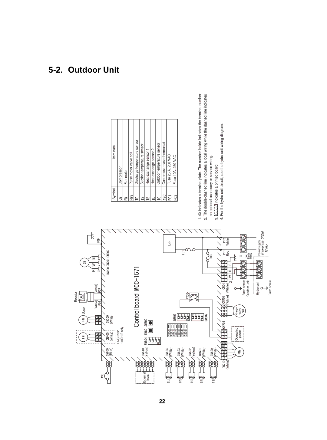
Wiring Diagram
Control board
Hot Water Cylinder Unit
Model name Component name Type name Rating M3-E T6-E
Key Electric Component Rating
HWS-802XWHM3-E, 802XWHT6-E
Model name Component name Type name Rating M3-E T6-E T9-E
US-622KXTMQO-SS
Component name Type name Rating
CAM-MD12TF-15
OFF = 125 ± 4 C, on = 90 ± 5 C
CSH
Model name Component name
Type name Rating
Thermal cut-out
Water Heat Exchange Control Board
F03 250 V, 10 a
P01Red P02White Earth lead wire P09 Black
Outdoor Control Board
D503 Green, Outdoor = Hydro
F700250V,3.15A
Water
Diagram
System Diagram
System
Installation example of water circuit
Outdoor unit Hydro unit
Refrigeration Cycle System Diagram
HWS-802XWHM3-E, 802XWHT6-E/802H-E
HWS-1402XWHM3-E, 1402XWHT6-E, 1402XWHT9-E/1102H-E, 1402H-E
Operational Description
Cooling Temperature setting
Operation Remote control settings
Heating Temperature setting
Hot water supply Temperature setting
Hydro unit
Hot water temperature 40C to 75C
Heating temperature 20C to 55C
Backup heater control
Outdoor unit
Cooling temperature 10C to 25C
Transmit
Hot water cylinder unit
Operation flow and applicable data, etc
TTW sensor
TWI
Zone Operation with heating priority
Pressing the ZONE1, 2 button and then Operation Mode
Starts a cooling operation
Pump priority
Simultaneous operations of hot water supply and cooling
75C Hot water operation
Switches to Hot water Supply operation
HOT Water button set to on HOT Water Boost button set to on
Heating side
Supply heater
HOT Water button set to on
Anti bacteria Anti Bacteria operation
Another 30 minutes can be set with FC0B
Night set back Night SET Back operation Operation
35B 30C 25D 20E
Nighttime low-noise operation Operation
Inverter output change
Hz signal correction
Controller set temperature
Temperature settings Water outlet temperature
TC=TWO
TC TWO
Keep
THO
Keep TSCF-4
TSCF-0
TSCF-2
Non-interlocked with the built-in pump
Circulation pump control Hydro Unit
SW3
Flow rateL/min
SW3 SW2
SW1
Heating operation Night Set Back
1Piping freeze prevention control
Automatic restart control
TWI, TWO, THO
Piping freeze prevention control
TWO
TCB-PCMO3E
Hydro Unit Room temperature thermostat control Option
PMV Pulse motor valve control
Main circuit control current
Settings Yes
Current degradation
Current release control
Number of rotation hold
TL C WE tap + 1 tap/20 secs
For 1402H-E
Hot water supply and heating fan control
For 802H-E
For 1102H-E
OFF
Heating operation starts
Inside brackets For 802H-E
Continuously energized
Not energized
Intermittently energized
Output equal to 40W
802H-E 1102H-E, 1402H-E Heating Cooling TC TWO+2 61C
Method of Defect Diagnosis
Procedure of defect diagnosis Remark
1 Non-defective operation
Check the power supply voltage
About the installation of the temperature sensor
Matters to be confirmed first
How to cancel a check code on the remote controller
Outline of the determination diagram
Procedure of defect diagnosis
How to determine from the check code on the remote control
3TWI
How to diagnose by error code
Defect mode detected by the water heat exchange
2TWO
Diagnostic functional operation Number
Diagnostic functional operation Number
Defect mode detected by the outdoor unit
Diagnostic functional operation Number
Diagnostic functional operation Number
Determination and action
Defect mode detected by the remote control
Diagnostic functional operation
Hydro unit failure detection
Diagnosis flow chart for each error code
A01 Error Pump flow determination
Yes Water outlet
A02 Error Temperature rise and error short circuit
Replace flow switch
Replace TWI, TWO, and THO sensors
Yes TTW 85C is detected Replace TTW sensor
A03 Error Temperature rise and error short circuit
Start
A04 Error Freeze prevention control
A05 Error Piping freeze prevention control
Place buffer tank
Yes Lower set temperature
Remove waste
Water circuit
Yes Defrost outdoor unit
Yes Raise set temperature
Where frost remains
Cooling overload operation
Put water into water circuit Recommended 1 2 Bar
Water cycle contains water
TWI sensor is Attach TWI sensor
A11 Error Release protection operation
Secure water Waste stuck inside Remove waste
A12 Error Heating or Hot water supply heater failure
E04 Error
Yes Replace water heat exchange control board
F03 Error TC sensor failure
F04 Error TD sensor failure
F06 Error TE sensor failure
F10 Error TWI sensor failure
F07 Error TL sensor failure
F08 Error to sensor failure
F17 Error TFI sensor failure
F11 Error TWO sensor failure
F14 Error TTW sensor failure
F19 Error THO sensor detach failure
F18 Error THO sensor failure
TFI s ensor Is attached to pipe
F20 Error TFI detach failure
F23 Error Lo pressure sensor detach failure
Lo pressure sensor Yes Is detached CN207 When operation
L09 Error
F29 Error Eeprom failure
F30 Error Enhanced IC failure
L07 Error
Outdoor Unit Failure Detection
Diagnosis procedure for each check code
Lock compressor Replace it Yes
Board side Wiring connection
Is normal Check and correct
Compressor is normal Yes
Eeprom failure → See F31 details
Heat sink temperature sensor TH failure → See F13 details
Communication failure between MCUs
Check outdoor control board If defective, replace it
Power voltage abnormally Yes
Is cleared, Blower is not blocked
Deal with short circuit Short circuit, etc Yes
Heat sink overheat failure
Outdoor control
SW804 SW801
Way valve invert failure
Element Short circuit
Heating operation
Yes Outdoor fan operates normally Check the same item as
Replace fan motor
Power voltage is normal Check wiring 230ACV ±
Diagram Yes
Correct wiring Replace outdoor board
Correct TE sensor
Characteristic table
TL sensor connector CN604 is connected
TL sensor resistance characteristic is normal
100
Suction temperature sensor TS failure
TS sensor resistance characteristic is normal
TD, TL sensors
101
TC, TWI, TWO, TFI, TTW, TE, TS, to sensors
Rotary Check contents Remark Switch
Operation check by PC board switch
Operation check mode
Operation check mode
103
Component name Check procedure
Brief method for checking the key components
Hydro unit
14.8 ± 1.5 Ω
Outdoor unit
104
802H-E 32.6 ± 3.3 Ω
105
10Hydro unit and Outdoor Unit Settings
Hydro unit Hydro unit Setting
106
Hydro unit Function Code Setting
Details First shipment
107
Nighttime low-noise end time
108
Details Fist shipment
109
Trial Operation
TSC-F
Auto Curve Setting
Set temperature A40 B35 C30 D25 E20 20 T1
110
111
Time Setting
112
Scheduled Operation Setting
Set temperature, day , and time
113
Frost Protection Setting
114
Night Operation Setting
115
Anti Bacteria Setting
116
Hot Water Boost Setting
Nighttime Low-noise Setting
117
Forced Defrosting Setting
Rated Operation Setting
118
Display Function of Set Temperature and Other Settings
119
Failure History Calling Function
120
Outdoor unit Outdoor Unit Setting
121
Function and details
122
123
LED indication
Item setting Temperature sensor
124
Current Compressor PMV openness Operation Pulse Frequency
SW804
Operation when press button switch SW801 is pressed
125
126
SW804 Operation when press button switch SW801 is pressed
127
11How to Exchange Main Parts
Work procedure Remarks
Hydro Unit
Controller holder
Remote controller cable
128
Remote
MgSW
Electric parts assembly
129
Relay board
130
Expansion vessel
Exchange parts name Work procedure Remarks
131
Board
132
Pump
Fixing
Manometer
Exchanger inlet pipe so that the wire is place on
133
134
135
136
Outdoor Unit 2-1. HWS-802H-E
137
CN202 Black
Remove the power source cable from the power
138
Lead
139
Fan motor lead Binding tie Compressor lead, Relay connector
Fan motor
140
Propeller fan Turn it right to loosen
Flange nut
141
142
143
Pulse motor
144
Spring
Valve body
145
146
Valve fixing board
Inverter assembly
147
Heat exchanger
Reactor lead CN05 White
148
Case thermostat, fan motor
Reactor lead Binding tie Reactor body
Name Electric parts Reactor Replacement 1Perform the step
149
Reactor lead
Fixing rubber Projection/Refrigerant cycle side Fan motor
150
Compressor nut 3 nuts
151
152
Positioning Motorized Projection Control valve coil
Pulse motor valve coil 1. How to remove 1Perform the step
153
Recess Pulse motor valve body
154
12Periodic Inspection Items
Inspection items
155
13Part Exploded View, Part List
156
157
002
158
Outdoor Unit
HWS802H-E
159
TD, TL sensor
Inverter Assembly HWS-802H-E
Sensor assembly 701 F6 TS, TE, TD sensor
160
161
Outdoor Unit HWS-1102H-E, 1402H-E
162
163
TS, TE, to sensor
Inverter Assembly HWS-1102H-E, 1402H-E
164
4316V357
165
43158190
Reactor
166