Agilent E5250A
Manual Part Number
Declaration of Conformity
Herstellerbescheinigung
Manufacturer’s Declaration
Safety Summary
Ground the Instrument
Use extreme caution when handling, testing, and adjusting
Do not Substitute Parts or Modify Instrument
Safety Symbols
CAT
This Manual
VXIplug&play Driver
Text Conventions
Page
Contents
Setting up Measurement Environment
Executing Self-Test and Leak Test
Controlling the E5250A
Programming the E5250A
Command Reference
Specifications Error Messages
VXIplug&play Driver
Executing Sample Programs
Scpi Command Summary
Introduction
Introduction
Agilent E5250A Product Description
Available Plug-in Cards for E5250A
Front Panel Tour
Rear Panel Tour
AUX Input
E5250A Rear Panel
E5252A Block Diagram
Agilent E5252A Product Description
May be present at the output connectors
E5252A Output Ports
Connectors
Agilent E5255A Product Description
Bias Input
IV Input
Resistors
By resistors must be less than 16W
E5255A Block Diagram
E5255A Input/Output Connectors ⋅8 multiplexer
Bias Input Output
Options and Accessories
Options Model Option Item Description Number
Furnished Accessories Model Part Number Description Qty
Virtual Front
VFP Data Upload
Capacitance Compensation
Available Accessories Model Option Description Number
Agilent E5250A User’s Guide, Edition
Installation
Installation
To Inspect the E5250A and Accessories
When shipping the E5250A
Power Requirements
Power Cable
Requirements
Installation
Operating Environment
Storage and Shipping Environment
Defeated
Installing the E5250A
To Install Plug-in Card
To Install Blank Panel
Module Extractor and Location of the Screw Hole
To Configure E5255A
Block Holder Cable Connector
To Modify IV Input
Multiplexer Blocks and Components
To Modify Bias Input
To Use Multiplexer Blocks on another E5255A
Agilent E5255A Component Locations
To Mount Protective Resistors
To Select Protective Resistors
E5255A Configuration Examples
Output multiplexer 3-BIAS inputs, 1-IV input, 1 module
Output multiplexer 3-BIAS inputs, 1-IV input, 1 module
Output multiplexer 1-BIAS input, 1-IV input, 1 module
Output multiplexer 1-BIAS input, 1-IV input, 1 module
Interconnection of Bias Input Connectors
To connect Bias inputs externally
Output multiplexer 1-BIAS input, 1-IV input, 4 modules
Output multiplexer 1-BIAS input, 1-IV input, 4 modules
To Set Gpib Address
To Connect Gpib Cable
Maintenance
Cleaning
Performance Verification
Executing Self-Test and Leak Test
Executing Self-Test and Leak Test
Performance Verification
Executing Self-Test
E5250A Self-Test Items Description Executed by Refer to
To Execute Self-Test Standalone
Executing the Controller Test
Executing the Relay Test
Settings after Relay Test
If Fail LED is on after Relay Test
Relay Test Adapter Connection
To Execute Self-Test using External Controller
Scpi Commands for Self-Test
Requirements
Before executing Relay Test, be careful about following
Scpi Commands for Self-Test Test Item Description
Front Panel Interface Test
Self-Test Programming Example
Assign
Line Number Description
Using the Self-Test Utility
Requirements
To Start the Self-Test Utility
Softkey Description
To Execute Self-Test
Example of Self Test Menu
Executing the Front Panel Interface Test
Fail Condition for Front Panel Interface Test
Continue
To Execute Leak Test
Start Test
YES
Message for non-Kelvin connection
Report CRT
Agilent E5250A User’s Guide, Edition
Setting up Measurement Environment
Setting up Measurement Environment
Connector Plates
Connector Plates for the E5252A
Connector Plates for E5255A
Blank Plate
16495E Half size blank plate
Connecting 8-Channel Shielded Coaxial Cable
Example of DUT Connection
Mounting Connectors Directly
Dimensions of Connector Holes
Recommended Parts Usage Agilent Part Description
To Install Interlock Circuit
Interlock Connector Pin Assignments
To Make Interlock Circuit
Dimensions of Interlock Switch Agilent part number
To Install LED Circuit
Dimensions of LED Agilent part number
Procedure
To Connect Interlock Circuit to Instrument
Required Parts Agilent Quantity Description Model No
To Check Interlock Circuit
To Connect Connectors to DUT
Connector Guard Sense Wire Insulator Plate
Low-Noise Coaxial Cable
Connecting the E5250A Input
To Connect Instruments to Input Connectors
Mpsmu
Shows an example of connecting the E5250A to
Connection Example with Agilent
To Connect Bias Source to the E5255A Bias Input
To Connect Gndu to the E5250A Input
Required Parts Agilent Quantity Description Model/Part No
SMU Input Port Number Input Signal
Connection of Triax-Dual Triax Adapter
Connecting the E5250A Output
E5252A Output Connector and Output Signal
To Connect the E5252A Output
E5252A Output Cable Agilent Model No Description
Kelvin Output Port Output Port Number
16494B Kelvin Triaxial Cable for E5252A
E5255A Output Connector and Output Signal
To Connect the E5255A Output
Measurement Cable Length
Guard Capacitances of E5250A Measurement Environment Typical
Controlling the E5250A
Controlling the E5250A
Methods for Controlling the E5250A
Creating Your Own Program
Capacitance Compensation Routine
Windows Workstation
Using the Virtual Front Panel VFP Utility
Modifying a Sample Program
VFP Data Upload Library
Switch Control Basics
Channel List and Channel Configuration
Syntax of channellist Parameter
Agilent E5250A User’s Guide, Edition
Channel Configuration
Normal
Auto
Connection Rule
Free
Connection Sequence
Connection Sequence Relay Operation
Bias Mode
Example of Bias Mode
Couple Port
Couple Port Number and Output Port Number
Couple Input Ports Available Output Port No
Couple Port Relay Connections
Normal Configuration Mode
E5252A Channel List
Switch Control Basics
E5252A Channel Number in Normal Config. Mode
Auto Configuration Mode
Controlling the E5250A
E5255A Channel List
E5255A Channel Number in Normal Config. Mode
Auto Configuration Mode
Example Setup of E5255A
SMU1
Example for E5255A Channel Number in Auto Config. Mode
Using Virtual Front Panel Utility
Functions of Virtual Front Panel Utility
Starting the Virtual Front Panel Utility
Model/Part No Description Qty
Confirming the E5250A Card Configurations
Mode
Changing the VFP Setup Mode
Channel Configuration mode
Bias Mode state of each card
Model Number of each card
To change the channel configuration mode
To change the Bias Mode state
To enter/cancel the changes and return to the VFP main menu
Example of Setup Mode Menu
Defining Labels for the E5250A Input Ports
To define labels for the E5250A input ports
To define labels for the E5255A bias input ports
Example of Define Label Menu
Making Connections and Changing the Setup Data
Next Setup
To change the E5250A setup to specified setup memory
To copy a setup memory
Example of Setup Memory Menu
To delete a setup memory
To insert a setup memory
To clear setup memory
To modify the settings in Current Setup Memory
Memory Setup Panel for the E5252A in Auto Config
Using Virtual Front Panel Utility
Chan
To enter a comment for the setup memory
To change the settings in a setup memory
Invalid Input Port
Softkey Menu
Moving the Cursor
ALL
Saving/Loading the Setup Data
To save setup data to diskette
To load setup data from diskette
Programming the E5250A
Programming the E5250A
Scpi Programming Basics
Scpi Command Hierarchy
Using a Semicolon to Reduce Typing
Controlling E5250A by Using HP Basic
Example
Creating a Control Program
Description Command Default Setting
Programming Summary
Defining Channel Configuration Mode
Command Description
Defining Connection Rule
Defining Connection Sequence
Using Bias Mode
Command Description
Using Couple Port for E5252A only
Routcoupport cardno ,`inputportno
Controlling Relay Switching
Routopen channellist
Programming Examples
E5250A Installed Cards
Channel Creation Example
Mosfet Connection Example
E5250A Input Ports
Program List
Line Description Number
Bias Mode Example
E5255A Connection
E5255A Output Ports
Example Using Bias Mode
Agilent E5250A User’s Guide, Edition
Couple Port Example
Example of Couple Port
Example Using Couple Port
Agilent E5250A User’s Guide, Edition
Using the VFP Data Upload Library
Initvfpsetup subprogram
VFP Data Upload Library
Loadvfpdata subprogram
Data string for internal use in the library. Must declare
Connectvfp subprogram
FNGetvfpcomment$ subprogram
Programming Example
Before Executing Your Program
Error Messages
Using the Capacitance Compensation Routine
Capacitance Compensation Routine
Freq
Using Other than Recommended Cable
Required Conditions
Measurement Parameter Frequency Function Terminals a
Program Line No Defines R, L, C value
GET Ccompen
Command Reference
ROUTe
SYSTem
Textual Notation for Subsystem Commands
Capital Letters
Common Commands
Common Commands for E5250A
Mnemonic Name
CLS
Command Reference *ESE
Bit Binary Description Weight
ESR?
IDN?
Response Type Explanation
OPC
Bias Mode
Bias Enabled Channels
Couple Port Mode
Connection Rule
SRE
Following four lines enable the same bits bit 4
STB?
TST?
DIAGnostic Subsystem
DIAGnostic Command Tree
Command Parameter
Parameter values
DIAGnosticTESTCARDCLEar
DIAGnosticTESTCARDEXECute?
Parameter Explanation
DIAGnosticTESTCARDSTATe?
DIAGnosticTESTFRAMeCLEar
DIAGnosticTESTFRAMeEXECute?
DIAGnosticTESTFRAMeSTATe?
ROUTe Command Tree
ROUTe Subsystem
Parameter values Cardnumber
ROUTeBIASCHANnelDISableCARD
ROUTeBIASCHANnelDISableLIST
ROUTeBIASCHANnelDISableLIST?
ROUTeBIASCHANnelENABleCARD
ROUTeBIASCHANnelENABleLIST
ROUTeBIASCHANnelENABleLIST?
ROUTeBIASPORT
ROUTeBIASPORT?
ROUTeBIASSTATe
ROUTeBIASSTATe?
ROUTeCLOSeCARD?
ROUTeCLOSeLIST
ROUTeCLOSeLIST?
ROUTeCONNectionRULE
ROUTeCONNectionRULE?
ROUTeCONNectionSEQuence
ROUTeCONNectionSEQuence?
ROUTeCOUPlePORT
Coupleport
ROUTeCOUPlePORT?
ROUTeCOUPleSTATe
ROUTeCOUPleSTATe?
ROUTeFUNCtion
ROUTeFUNCtion?
ROUTeOPENCARD
ROUTeOPENLIST
ROUTeOPENLIST?
SYSTem Command Tree
SYSTem Subsystem
SYSTemCCONfig?
Cardconfiguration newlineEND
SYSTemCDEScription?
Following
SYSTemCPON
SYSTemCTYPe?
SYSTemERRor?
SYSTemVERSion?
Status Reporting Structure
Status Reporting Structure
Status Reporting Structure of E5250A
Status Byte Register
Status Byte Register of E5250A
Status Byte Register of E5250A Bit Definition Explanation
Service Request Enable Register
Service Request Enable Register of E5250A
Standard Event Status Register
Standard Event Status Register of E5250A
Standard Event Status Enable Register
Bit Definition Explanation
Output Queue
Output Queue of E5250A
Agilent E5250A User’s Guide, Edition
VXIplug&play Driver
VXIplug&play Driver
System Requirements
Installing VXIplug&play Driver
Driver Functions
E5250A Driver Function Lists
Category Function Description
Agilent E5250A User’s Guide, Edition
Hpe5250abiasChanCard
Hpe5250abiasChanList
Hpe5250abiasChanListQ
Biasdisen
Biasstatus
Hpe5250abiasPort
Hpe5250abiasState
Hpe5250aclose
Hpe5250acloseCardQ
Closecard
Hpe5250acloseList
Hpe5250acloseListQ
Hpe5250acmd
Closestatus
Cmdstr
Hpe5250acmdDataQ
Hpe5250acmdInt
Size
Result
Hpe5250acmdInt16ArrQ
Hpe5250acmdInt16Q
Count
Hpe5250acmdInt32ArrQ
Hpe5250acmdInt32Q
Hpe5250acmdReal
Hpe5250acmdReal64ArrQ
Hpe5250acmdReal64Q
Hpe5250acmdStringQ
Hpe5250acompenC
Hpe5250aconnRuleSeq
Cardnoruleseq
Rule
Sequence
Hpe5250acouplePort
Hpe5250acoupleState
Hpe5250adcl
Couplestatecardn
Couplestate
Hpe5250aerrormessage
Hpe5250aerrorquery
Errornumber
Message
Hpe5250aerrorQueryDetect
Hpe5250aerrorQueryDetectQ
PErrDetect
Channelconfig
Hpe5250aesrQ
Hpe5250afunc
Errstr
Doreset
Hpe5250ainit
Hpe5250aopcQ
InstrDesc
Hpe5250aopenCard
Hpe5250aopenList
Opencardno
Hpe5250aopenListQ
Hpe5250areadStatusByteQ
Openstatus
StatusByte
Hpe5250areset
Hpe5250arevisionquery
Driverrev
Instrrev
Hpe5250aselectCompenFile
Filename
Hpe5250aselftest
Hpe5250atestClear
Testresult
Testmessage
Hpe5250atimeOut
Hpe5250atimeOutQ
Hpe5250atestExecQ
Agilent E5250A User’s Guide, Edition
Executing Sample Programs
Executing Sample Programs
To Keep Original Program Disk
Vth and Capacitance Measurement Program
Introduction
Vth and Capacitance Measurement Flow
Step Description
Vth Measurement Setup
Channel/Source Setup
Source Setup
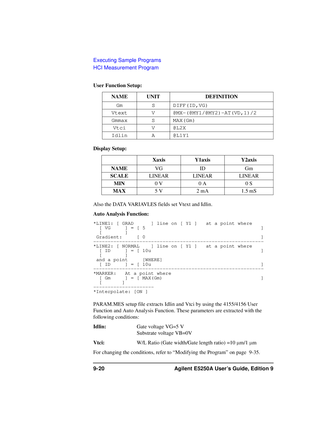
User Function Setup
Capacitance Measurement Setup
Display Setup Xaxis Y1axis Y2axis
Auto Analysis Setup
Setting up the Measurement Environment
Required Equipments Agilent Model/Part No Description Qty
Vth and C Measurement Setup and DUT Connection
Vth and Capacitance Measurement Program
Executing the Program
Example of Vth and C Measurement Results
Parameter Description Default
Modifying the Program
To change the Gpib Address
To change the header of the measurement result report
To output the measurement report to printer
To execute the 4155/4156 calibration
To save the 4155/4156 measurement data
To change the Vth measurement setup
To change the capacitance measurement setup
To use the VFP data upload library
Subprogram Program Line
Constant Definition
HCI Measurement Program
To Add the Bias Source Control Routine
Determines Stress Condition
Test Device for Defining Stress Conditions
Selects devices valid for the HCI test
Characterizes the initial parameters
Device Device2 Terminal
Auto Analysis Function
Applies stress and characterizes the parameters
Stress Stress time Cumulative Cycle
Required Equipments
Required Equipment Agilent Model/Part No Description Qty
Adding the Bias Source Control Routine
Subend
Setting up the Measurement Environment
Internal Connections and DIP SW Settings for E5255As
E5250A Input/Output Connection
E5250A Input Measurement E5255A Output Port
Port
DC HCI Degradation Test Equipment Connections
Device used to Determine Stress Conditions
Load Spmux Edit
Id-Vds Measurement Example
To Execute HCI Test Program
Example of Ib-Vgs Measurement Results
Initial/Interim Characterization Example
HCI Degradation Test Result Example
To Execute Analysis Program
HCI Degradation Test Data Analysis Example
Number of devices Vdstr, Vgstr, Gate length, Gate width
Modifying the Program
To change the 4155/4156 setup file used
To change Vtci extraction condition
To change Idlin and Gmmax extraction condition
To change the number of devices
To change the stress times
To change the test limits
To specify the data displayed on the 4155/4156 screen
To change the timing for saving the test data
Specifications
10-2 Agilent E5250A User’s Guide, Edition
General Specifications
Dimensions
Agilent E5252A 10x12 Matrix Switch
Switch Specifications
Typical Data
Supplemental Data
Agilent E5255A 24 8x3 Channel Multiplexer
10-6 Agilent E5250A User’s Guide, Edition
Low Leakage I-V Port
Accessories
Operating To 40 C Storage −40 C to 70 C
Operating
Supplemental Data when used with Agilent 4155/4156
Supplemental Data when used with Agilent
Range Setting Measurement
10-10 Agilent E5250A User’s Guide, Edition
Error Messages
Error Range Error Category
Error Category Standard Event
Standard Scpi Error Messages
Command Error
Data type error
Command header error
Header separator error
Invalid separator
Numeric data error
Character data error
Invalid character in number
Exponent too large
String data error
Block data error
Expression error
Character data not allowed
Execution Error
Device-Dependent Errors
Device-specific error
Memory error
Queue overflow
Query Errors
E5250A Specific Error Messages
E5250A Channel Related Errors
E5250A Card/Mode/Port Related Errors
Cannot connect multiple channels in SROUTe mode
Config error. Re-install E5255A
Cant change to ACONfig mode. Check card config
Cannot directly specify Bias Port channel
11-14 Agilent E5250A User’s Guide, Edition
Scpi Command Summary
12-2 Agilent E5250A User’s Guide, Edition
Agilent E5250A User’s Guide, Edition 12-3
12-4 Agilent E5250A User’s Guide, Edition
Agilent E5250A User’s Guide, Edition 12-5
12-6 Agilent E5250A User’s Guide, Edition
Agilent E5250A User’s Guide, Edition 12-7
12-8 Agilent E5250A User’s Guide, Edition