Chapter 3 Installing a Cisco 7500 Series Router
Installing the Cisco 7513, Cisco
R E V I E W D R A F T — C I S CO CO N F I D E N T I A L
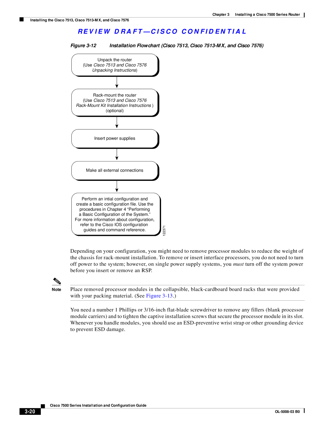
Figure 3-12 Installation Flowchart (Cisco 7513, Cisco 7513-MX, and Cisco 7576)
Unpack the router
(Use Cisco 7513 and Cisco 7576
Unpacking Instructions)
(Use Cisco 7513 and Cisco 7576
(optional)
Insert power supplies
Make all external connections
Perform an intial configuration and
create a basic configuration file. Use the procedures in Chapter 4 “Performing a Basic Configuration of the System.”
For more information about configuration,
refer to the Cisco IOS configuration | 122371 | |
guides and command reference. | ||
|
Depending on your configuration, you might need to remove processor modules to reduce the weight of the chassis for
Note Place removed processor modules in the collapsible,
You need a number 1 Phillips or
| Cisco 7500 Series Installation and Configuration Guide |