Chapter 7 Maintaining Your Cisco 7513, Cisco
Maintenance Procedures for the Cisco 7513, Cisco
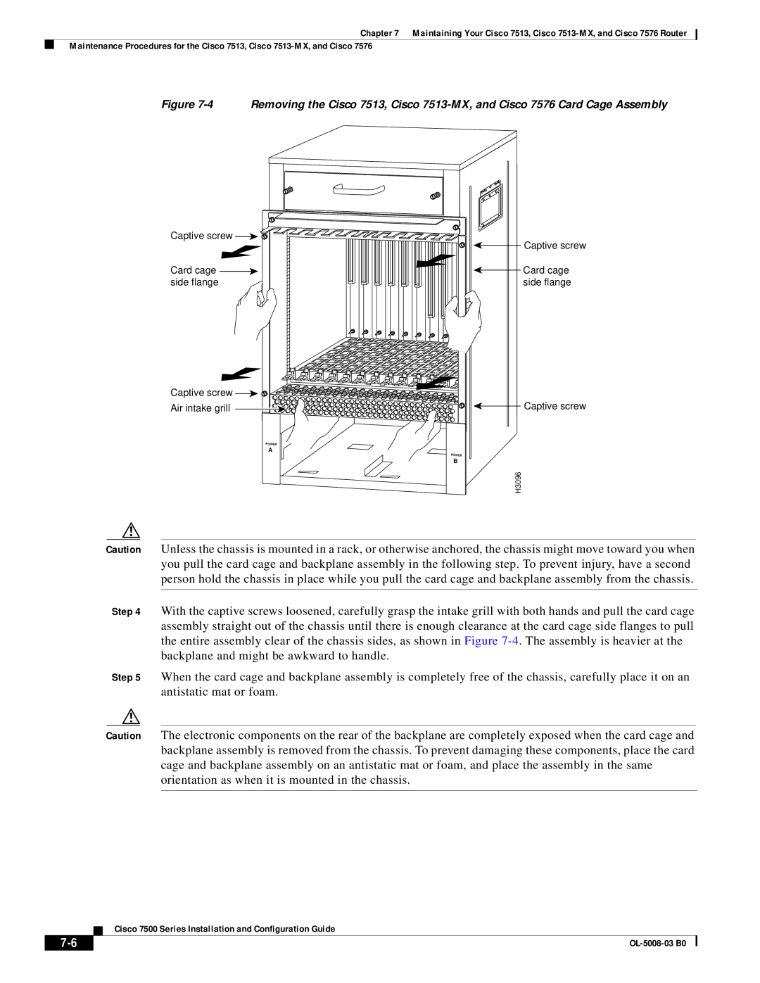
Figure 7-4 Removing the Cisco 7513, Cisco 7513-MX, and Cisco 7576 Card Cage Assembly
Captive screw | Captive screw |
| |
Card cage | Card cage |
side flange | side flange |
Captive screw ![]()
![]()
Air intake grill ![]()
![]()
![]()
![]()
![]()
![]()
![]()
![]()
![]()
![]()
![]()
![]()
![]()
![]()
![]()
![]()
![]()
![]()
![]()
![]()
![]()
![]()
![]()
![]()
![]()
![]()
![]()
![]()
![]()
![]()
![]()
![]()
![]()
![]()
![]()
![]()
![]()
![]()
![]()
![]()
![]()
![]()
![]()
![]()
![]()
![]()
![]()
![]()
![]()
![]()
![]()
![]()
![]()
![]()
![]()
![]()
![]()
![]()
![]()
![]()
![]()
![]()
![]()
![]()
![]()
![]()
![]()
![]()
![]()
![]()
![]()
![]()
![]()
![]()
![]()
![]()
![]()
![]()
![]()
![]()
![]()
![]()
![]()
![]()
![]()
![]()
![]()
![]()
![]()
![]()
![]()
![]()
![]()
![]()
![]()
![]()
![]()
![]()
![]()
![]()
![]()
![]() Captive screw
Captive screw
POWER
A
POWER
B
H3096
Caution Unless the chassis is mounted in a rack, or otherwise anchored, the chassis might move toward you when you pull the card cage and backplane assembly in the following step. To prevent injury, have a second person hold the chassis in place while you pull the card cage and backplane assembly from the chassis.
Step 4 With the captive screws loosened, carefully grasp the intake grill with both hands and pull the card cage assembly straight out of the chassis until there is enough clearance at the card cage side flanges to pull the entire assembly clear of the chassis sides, as shown in Figure
Step 5 When the card cage and backplane assembly is completely free of the chassis, carefully place it on an antistatic mat or foam.
Caution The electronic components on the rear of the backplane are completely exposed when the card cage and backplane assembly is removed from the chassis. To prevent damaging these components, place the card cage and backplane assembly on an antistatic mat or foam, and place the assembly in the same orientation as when it is mounted in the chassis.
Cisco 7500 Series Installation and Configuration Guide
|
| |
|