Chapter 2 Preparing for Installation
Site Environment, Chassis Temperature, and Airflow Guidelines
specifications for the electrical interfaces supported by the Cisco 7500 series routers, refer to the
companion publication Interface Processor Installation and Configuration Guide.
Site Environment, Chassis Temperature, and Airflow Guidelines
Cisco 7500 series routers can operate as standalone systems placed on a table or as
The internal fan or blower operates so that it maintains an acceptable operating temperature inside the chassis. The router requires a dry, clean,
To help maintain normal operation and avoid unnecessary maintenance, plan your site configuration and prepare your site before installation. After installation, make sure that the site maintains an ambient temperature of 32 through 104°F (0 through 40°C), and keep the area around the chassis as free from dust as is practical. For a description of the environmental monitor and status levels, see the “Environmental Monitoring and Reporting Overview for the Cisco 7500 Series” section on page
If the temperature of the air drawn into the chassis is higher than desirable, the air temperature inside the chassis might also be too high. This condition can occur when the wiring closet or rack in which the chassis is mounted is not ventilated properly, when the exhaust of one device is placed so it enters the air inlet vent of the chassis, or when the chassis is the top unit in an unventilated rack. Any of these conditions can inhibit airflow and create an overtemperature condition.
Because the inlet air flows into one part of the chassis and out another, other devices can be
Table
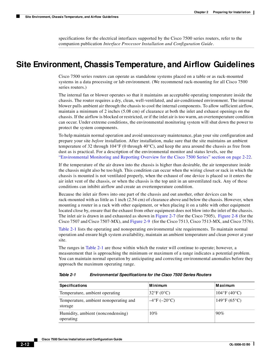
The ranges in Table
|
|
|
| Table | Environmental Specifications for the Cisco 7500 Series Routers |
|
| |
|
|
|
|
|
|
|
| |
|
|
|
| Specifications |
| Minimum | Maximum | |
|
|
|
|
|
|
| ||
|
|
|
| Temperature, ambient operating | 32°F (0°C) | 104°F (40°C) | ||
|
|
|
|
|
|
| ||
|
|
|
| Temperature, ambient nonoperating and | 149°F (65°C) | |||
|
|
|
| storage |
|
|
|
|
|
|
|
|
|
|
|
| |
|
|
|
| Humidity, ambient (noncondensing) | 10% | 90% |
| |
|
|
|
| operating |
|
|
|
|
|
|
|
|
|
|
|
| |
|
|
| Cisco 7500 Series Installation and Configuration Guide |
|
|
| ||
|
|
|
|
|
| |||
|
|
|
|
|
|
|
| |
|
|
|
|
|
|
| ||