Chapter 1 Cisco 7500 Series Product Overview
Interface Processor Overview
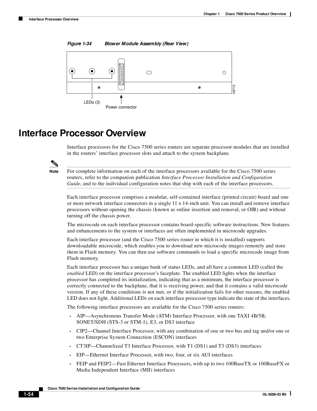
Figure 1-34 Blower Module Assembly (Rear View)
H9715
LEDs (3)
Power connector
Interface Processor Overview
Interface processors for the Cisco 7500 series routers are separate processor modules that are installed in the routers’ interface processor slots and attach to the system backplane.
Note For complete information on each of the interface processors available for the Cisco 7500 series routers, refer to the companion publication Interface Processor Installation and Configuration Guide, and to the individual configuration notes that ship with each of the interface processors.
Each interface processor comprises a modular,
The microcode on each interface processor contains
Each interface processor (and the Cisco 7500 series router in which it is installed) supports downloadable microcode, which enables you to download new microcode images remotely and store them in Flash memory. You can then use software commands to load a specific microcode image from Flash memory.
Each interface processor has a unique bank of status LEDs, and all have a common LED (called the enabled LED) on the interface processor’s faceplate. The enabled LED lights when the interface processor has completed its initialization, indicating that as a minimum, the interface processor is correctly connected to the backplane, that it is receiving power, and that it contains a valid microcode version. If any of these conditions is not met, or if the initialization fails for other reasons, the enabled LED does not light. Additional LEDs on each interface processor type indicate the state of the interfaces.
The following interface processors are available for the Cisco 7500 series routers:
•
•
•
•
•FEIP and
| Cisco 7500 Series Installation and Configuration Guide |