Chapter 2 Preparing for Installation
Environmental Monitoring and Reporting Overview for the Cisco 7500 Series
+24(V) |
| 20.00 |
| 23.80(V) | 28.00 |
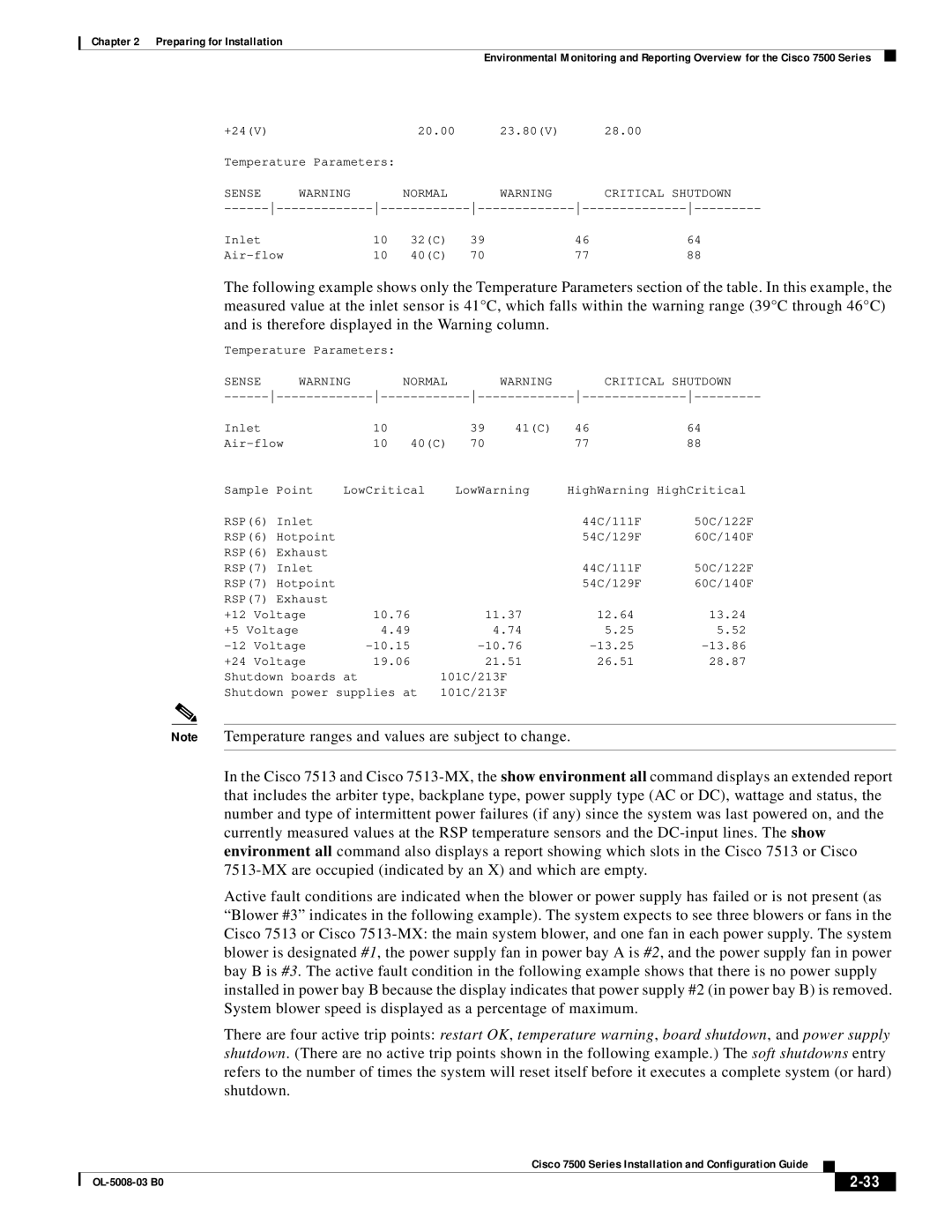
Temperature Parameters: |
|
|
|
| |
SENSE | WARNING | NORMAL |
| WARNING | CRITICAL SHUTDOWN |
Inlet | 10 | 32(C) | 39 | 46 | 64 |
10 | 40(C) | 70 | 77 | 88 | |
The following example shows only the Temperature Parameters section of the table. In this example, the measured value at the inlet sensor is 41°C, which falls within the warning range (39°C through 46°C) and is therefore displayed in the Warning column.
Temperature Parameters: |
|
|
|
|
| ||
SENSE | WARNING |
| NORMAL |
| WARNING |
| CRITICAL SHUTDOWN |
Inlet |
| 10 |
| 39 | 41(C) | 46 | 64 |
| 10 | 40(C) | 70 |
| 77 | 88 | |
Sample Point | LowCritical | LowWarning | HighWarning HighCritical | |
RSP(6) Inlet |
|
| 44C/111F | 50C/122F |
RSP(6) Hotpoint |
|
| 54C/129F | 60C/140F |
RSP(6) Exhaust |
|
|
|
|
RSP(7) Inlet |
|
| 44C/111F | 50C/122F |
RSP(7) Hotpoint |
|
| 54C/129F | 60C/140F |
RSP(7) Exhaust |
|
|
|
| |
+12 | Voltage | 10.76 | 11.37 | 12.64 | 13.24 |
+5 Voltage | 4.49 | 4.74 | 5.25 | 5.52 | |
Voltage | |||||
+24 | Voltage | 19.06 | 21.51 | 26.51 | 28.87 |
Shutdown boards at |
| 101C/213F |
|
| |
Shutdown power supplies at | 101C/213F |
|
| ||
Note Temperature ranges and values are subject to change.
In the Cisco 7513 and Cisco
Active fault conditions are indicated when the blower or power supply has failed or is not present (as “Blower #3” indicates in the following example). The system expects to see three blowers or fans in the Cisco 7513 or Cisco
There are four active trip points: restart OK, temperature warning, board shutdown, and power supply shutdown. (There are no active trip points shown in the following example.) The soft shutdowns entry refers to the number of times the system will reset itself before it executes a complete system (or hard) shutdown.
|
| Cisco 7500 Series Installation and Configuration Guide |
|
| |
|
|
| |||
|
|
|
|
| |
|
|
|
| ||