Chapter 5 Maintaining Your Cisco 7505 Router
Maintenance Procedures for the Cisco 7505
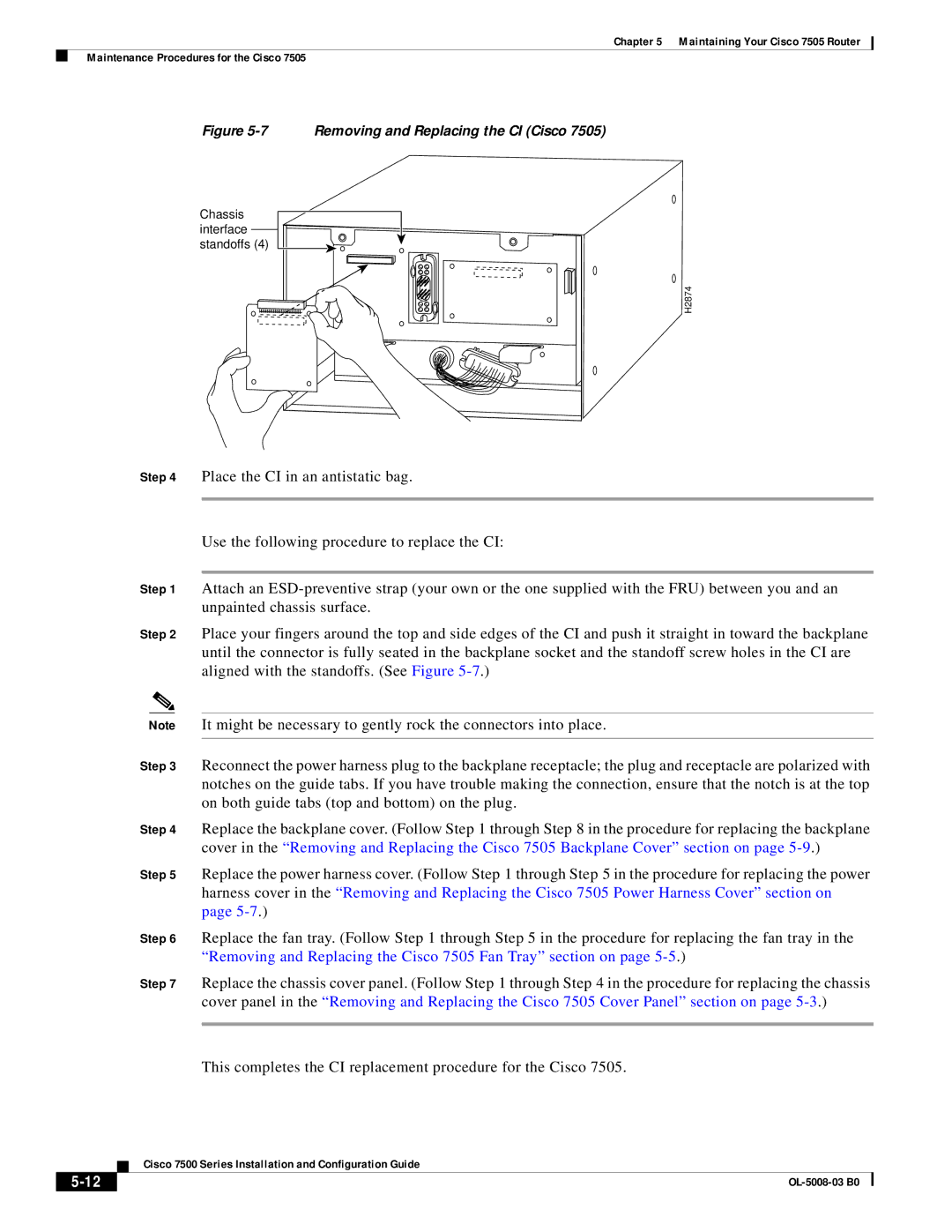
Figure 5-7 Removing and Replacing the CI (Cisco 7505)
Chassis interface standoffs (4)
H2874
Step 4 Place the CI in an antistatic bag.
Use the following procedure to replace the CI:
Step 1 Attach an
Step 2 Place your fingers around the top and side edges of the CI and push it straight in toward the backplane until the connector is fully seated in the backplane socket and the standoff screw holes in the CI are aligned with the standoffs. (See Figure
Note It might be necessary to gently rock the connectors into place.
Step 3 Reconnect the power harness plug to the backplane receptacle; the plug and receptacle are polarized with notches on the guide tabs. If you have trouble making the connection, ensure that the notch is at the top on both guide tabs (top and bottom) on the plug.
Step 4 Replace the backplane cover. (Follow Step 1 through Step 8 in the procedure for replacing the backplane cover in the “Removing and Replacing the Cisco 7505 Backplane Cover” section on page
Step 5 Replace the power harness cover. (Follow Step 1 through Step 5 in the procedure for replacing the power harness cover in the “Removing and Replacing the Cisco 7505 Power Harness Cover” section on page
Step 6 Replace the fan tray. (Follow Step 1 through Step 5 in the procedure for replacing the fan tray in the “Removing and Replacing the Cisco 7505 Fan Tray” section on page
Step 7 Replace the chassis cover panel. (Follow Step 1 through Step 4 in the procedure for replacing the chassis cover panel in the “Removing and Replacing the Cisco 7505 Cover Panel” section on page
This completes the CI replacement procedure for the Cisco 7505.
| Cisco 7500 Series Installation and Configuration Guide |
|