Chapter 6 Maintaining Your Cisco 7507 and Cisco
Maintenance Procedures for the Cisco 7507 and Cisco
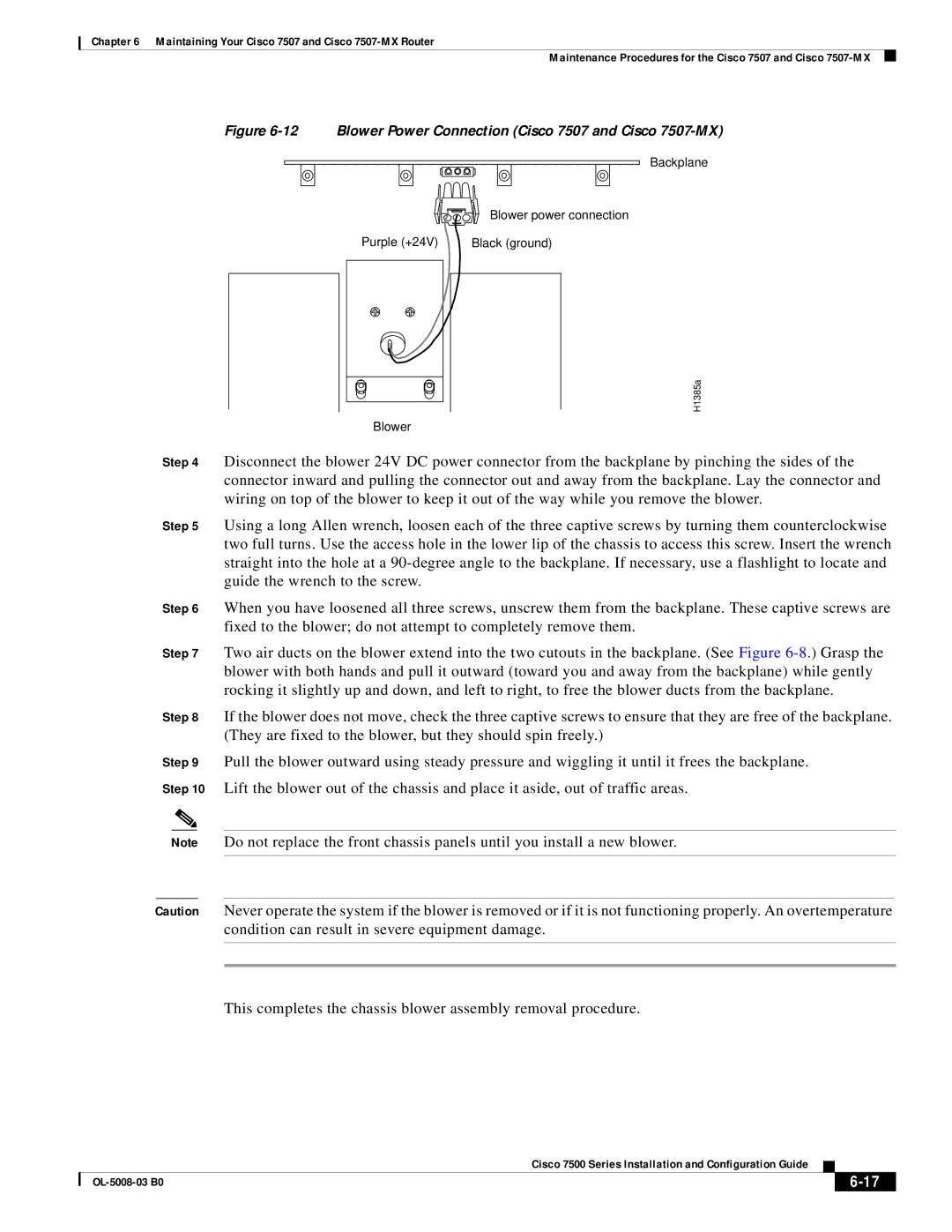
Figure 6-12 Blower Power Connection (Cisco 7507 and Cisco 7507-MX)
Backplane
Blower power connection
Purple (+24V) | Black (ground) |
H1385a
Blower
Step 4 Disconnect the blower 24V DC power connector from the backplane by pinching the sides of the connector inward and pulling the connector out and away from the backplane. Lay the connector and wiring on top of the blower to keep it out of the way while you remove the blower.
Step 5 Using a long Allen wrench, loosen each of the three captive screws by turning them counterclockwise two full turns. Use the access hole in the lower lip of the chassis to access this screw. Insert the wrench straight into the hole at a
Step 6 When you have loosened all three screws, unscrew them from the backplane. These captive screws are fixed to the blower; do not attempt to completely remove them.
Step 7 Two air ducts on the blower extend into the two cutouts in the backplane. (See Figure
Step 8 If the blower does not move, check the three captive screws to ensure that they are free of the backplane. (They are fixed to the blower, but they should spin freely.)
Step 9 Pull the blower outward using steady pressure and wiggling it until it frees the backplane. Step 10 Lift the blower out of the chassis and place it aside, out of traffic areas.
Note Do not replace the front chassis panels until you install a new blower.
Caution Never operate the system if the blower is removed or if it is not functioning properly. An overtemperature condition can result in severe equipment damage.
This completes the chassis blower assembly removal procedure.
|
| Cisco 7500 Series Installation and Configuration Guide |
|
| |
|
|
| |||
|
|
|
|
| |
|
|
|
| ||