Chapter 1 Cisco 7500 Series Product Overview
Route Switch Processor Overview
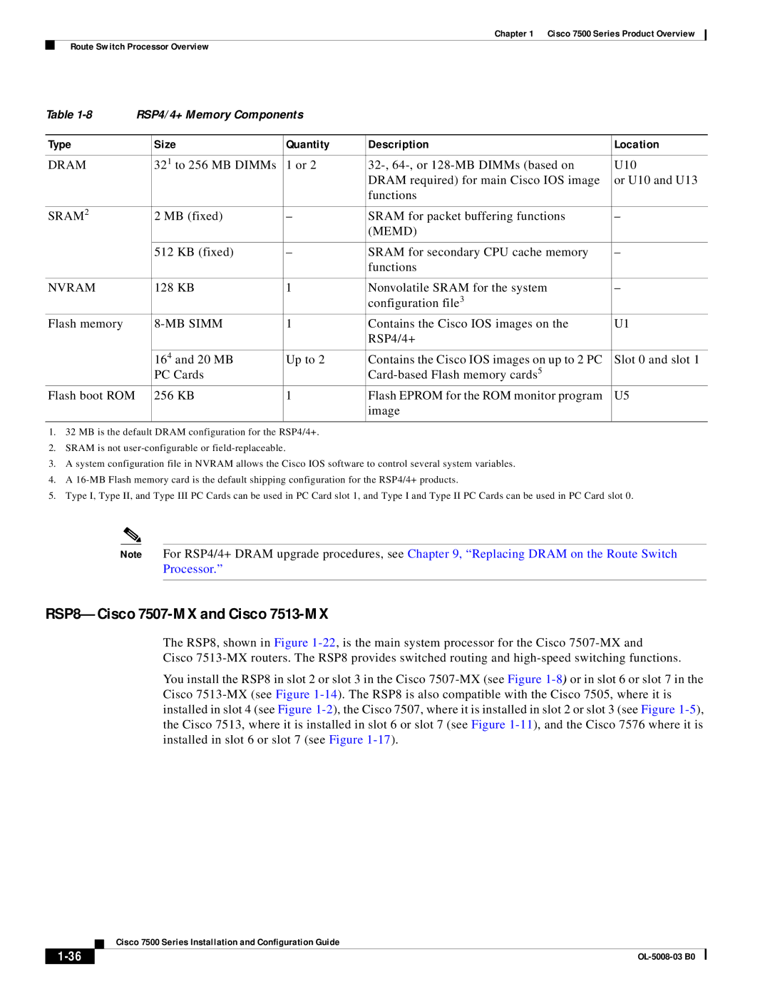
Table | RSP4/4+ Memory Components |
|
| ||
|
|
|
|
|
|
Type |
| Size | Quantity | Description | Location |
|
|
|
|
|
|
DRAM |
| 321 to 256 MB DIMMs | 1 or 2 | U10 | |
|
|
|
| DRAM required) for main Cisco IOS image | or U10 and U13 |
|
|
|
| functions |
|
|
|
|
|
|
|
SRAM2 |
| 2 MB (fixed) | – | SRAM for packet buffering functions | – |
|
|
|
| (MEMD) |
|
|
|
|
|
|
|
|
| 512 KB (fixed) | – | SRAM for secondary CPU cache memory | – |
|
|
|
| functions |
|
|
|
|
|
|
|
NVRAM |
| 128 KB | 1 | Nonvolatile SRAM for the system | – |
|
|
|
| configuration file3 |
|
Flash memory |
|
| 1 | Contains the Cisco IOS images on the | U1 |
|
|
|
| RSP4/4+ |
|
|
|
|
|
|
|
|
| 164 and 20 MB | Up to 2 | Contains the Cisco IOS images on up to 2 PC | Slot 0 and slot 1 |
|
| PC Cards |
|
| |
Flash boot ROM |
| 256 KB | 1 | Flash EPROM for the ROM monitor program | U5 |
|
|
|
| image |
|
|
|
|
|
|
|
1.32 MB is the default DRAM configuration for the RSP4/4+.
2.SRAM is not
3.A system configuration file in NVRAM allows the Cisco IOS software to control several system variables.
4.A
5.Type I, Type II, and Type III PC Cards can be used in PC Card slot 1, and Type I and Type II PC Cards can be used in PC Card slot 0.
Note For RSP4/4+ DRAM upgrade procedures, see Chapter 9, “Replacing DRAM on the Route Switch Processor.”
RSP8—Cisco 7507-MX and Cisco 7513-MX
The RSP8, shown in Figure
Cisco
You install the RSP8 in slot 2 or slot 3 in the Cisco
| Cisco 7500 Series Installation and Configuration Guide |
