Chapter 2 Preparing for Installation
Environmental Monitoring and Reporting Overview for the Cisco 7500 Series
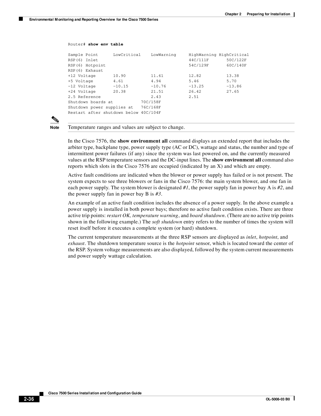
Router# show env table |
|
|
| ||
Sample Point | LowCritical | LowWarning | HighWarning HighCritical | ||
RSP(6) Inlet |
|
| 44C/111F | 50C/122F | |
RSP(6) Hotpoint |
|
| 54C/129F | 60C/140F | |
RSP(6) Exhaust |
|
|
|
| |
+12 | Voltage | 10.90 | 11.61 | 12.82 | 13.38 |
+5 Voltage | 4.61 | 4.94 | 5.46 | 5.70 | |
Voltage | |||||
+24 | Voltage | 20.38 | 21.51 | 26.42 | 27.65 |
2.5 | Reference |
| 2.43 | 2.51 |
|
Shutdown boards at |
| 70C/158F |
|
| |
Shutdown power supplies at | 76C/168F |
|
| ||
Restart after shutdown below 40C/104F
Note Temperature ranges and values are subject to change.
In the Cisco 7576, the show environment all command displays an extended report that includes the arbiter type, backplane type, power supply type (AC or DC), wattage and status, the number and type of intermittent power failures (if any) since the system was last powered on, and the currently measured values at the RSP temperature sensors and the
Active fault conditions are indicated when the blower or power supply has failed or is not present. The system expects to see three blowers or fans in the Cisco 7576: the main system blower, and one fan in each power supply. The system blower is designated #1, the power supply fan in power bay A is #2, and the power supply fan in power bay B is #3.
An example of an active fault condition includes the absence of a power supply. In the above example a power supply is installed in both power bays; therefore no active fault condition exists. There are three active trip points: restart OK, temperature warning, and board shutdown. (There are no active trip points shown in the following example.) The soft shutdown entry refers to the number of times the system will reset itself before it executes a complete system (or hard) shutdown.
The current temperature measurements at the three RSP sensors are displayed as inlet, hotpoint, and exhaust. The shutdown temperature source is the hotpoint sensor, which is located toward the center of the RSP. System voltage measurements are also displayed, followed by the system current measurements and power supply wattage calculation.
| Cisco 7500 Series Installation and Configuration Guide |