Chapter 7 Maintaining Your Cisco 7513, Cisco
Maintenance Procedures for the Cisco 7513, Cisco
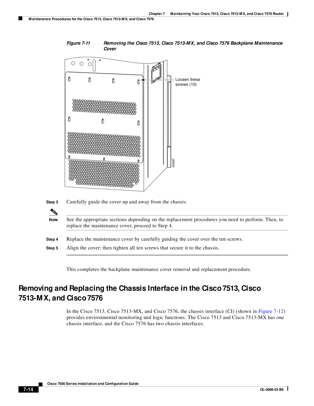
Figure 7-11 Removing the Cisco 7513, Cisco 7513-MX, and Cisco 7576 Backplane Maintenance Cover

 Loosen these screws (10)
H3097
Step 3 Carefully guide the cover up and away from the chassis.
Note See the appropriate sections depending on the replacement procedures you need to perform. Then, to replace the maintenance cover, proceed to Step 4.
Step 4 Replace the maintenance cover by carefully guiding the cover over the ten screws.
Step 5 Align the cover; then tighten all ten screws that secure it to the chassis.
This completes the backplane maintenance cover removal and replacement procedure.
Removing and Replacing the Chassis Interface in the Cisco 7513, Cisco
In the Cisco 7513, Cisco
| Cisco 7500 Series Installation and Configuration Guide |
|