Chapter 3 Installing a Cisco 7500 Series Router
Installing the Cisco 7513, Cisco
R E V I E W D R A F T — C I S CO CO N F I D E N T I A L
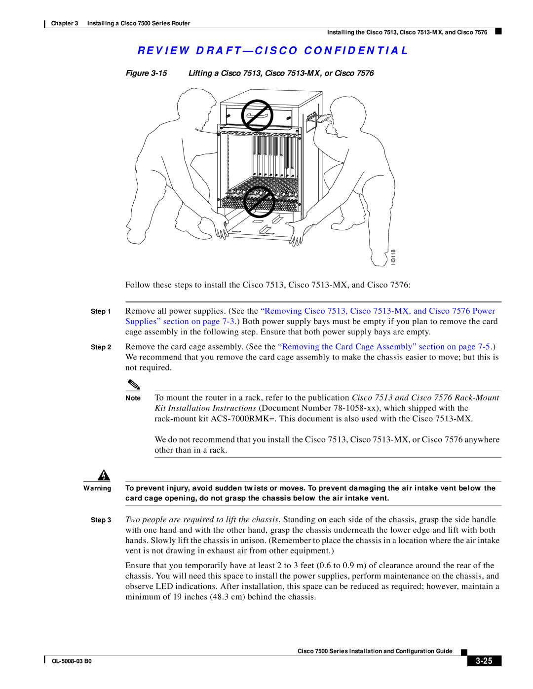
Figure 3-15 Lifting a Cisco 7513, Cisco 7513-MX, or Cisco 7576
POWER
A
POWER
B
H3118
Follow these steps to install the Cisco 7513, Cisco
Step 1 Remove all power supplies. (See the “Removing Cisco 7513, Cisco
Step 2 Remove the card cage assembly. (See the “Removing the Card Cage Assembly” section on page
Note To mount the router in a rack, refer to the publication Cisco 7513 and Cisco 7576
We do not recommend that you install the Cisco 7513, Cisco
Warning To prevent injury, avoid sudden twists or moves. To prevent damaging the air intake vent below the card cage opening, do not grasp the chassis below the air intake vent.
Step 3 Two people are required to lift the chassis. Standing on each side of the chassis, grasp the side handle with one hand and with the other hand, grasp the chassis underneath the lower edge and lift with both hands. Slowly lift the chassis in unison. (Remember to place the chassis in a location where the air intake vent is not drawing in exhaust air from other equipment.)
Ensure that you temporarily have at least 2 to 3 feet (0.6 to 0.9 m) of clearance around the rear of the chassis. You will need this space to install the power supplies, perform maintenance on the chassis, and observe LED indications. After installation, this space can be reduced as required; however, maintain a minimum of 19 inches (48.3 cm) behind the chassis.
|
| Cisco 7500 Series Installation and Configuration Guide |
|
| |
|
|
| |||
|
|
|
|
| |
|
|
|
| ||