Chapter 3 Installing a Cisco 7500 Series Router
Installing the Cisco 7513, Cisco
R E V I E W D R A F T — C I S CO CO N F I D E N T I A L
Caution To maintain agency compliance requirements and meet EMI emissions standards in the Cisco 7513, Cisco
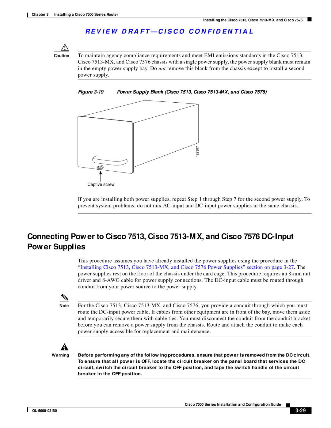
Figure 3-19 Power Supply Blank (Cisco 7513, Cisco 7513-MX, and Cisco 7576)
122307
Captive screw
If you are installing both power supplies, repeat Step 1 through Step 7 for the second power supply. To prevent system problems, do not mix
Connecting Power to Cisco 7513, Cisco
This procedure assumes you have already installed the power supplies using the procedure in the “Installing Cisco 7513, Cisco
Note For the Cisco 7513, Cisco
Warning Before performing any of the following procedures, ensure that power is removed from the DC circuit. To ensure that all power is OFF, locate the circuit breaker on the panel board that services the DC circuit, switch the circuit breaker to the OFF position, and tape the switch handle of the circuit breaker in the OFF position.
|
| Cisco 7500 Series Installation and Configuration Guide |
|
| |
|
|
| |||
|
|
|
|
| |
|
|
|
| ||