Chapter 7 Maintaining Your Cisco 7513, Cisco
Maintenance Procedures for the Cisco 7513, Cisco
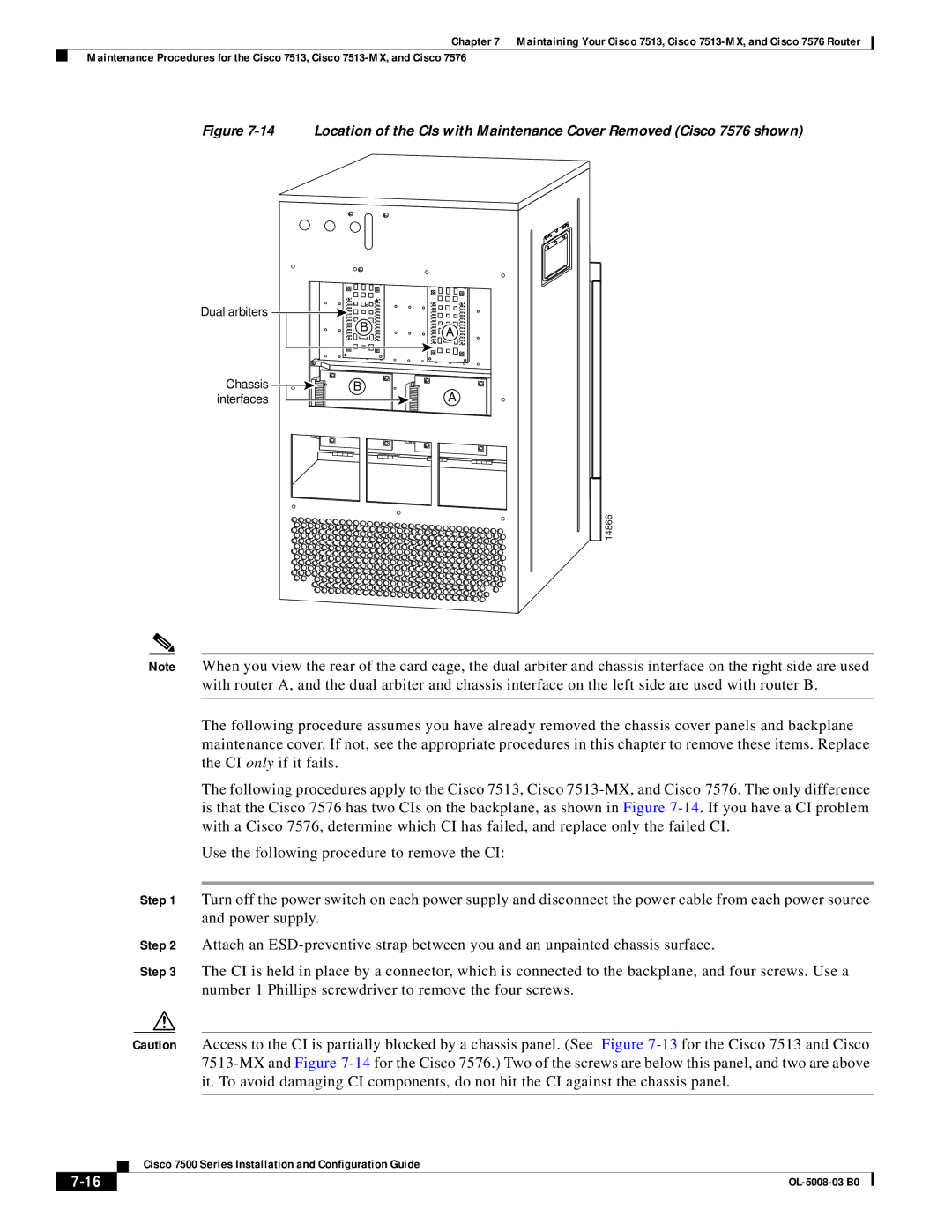
Figure 7-14 Location of the CIs with Maintenance Cover Removed (Cisco 7576 shown)
Dual arbiters
B
Chassis 
 B
B 

 interfaces

A
A
14866
Note When you view the rear of the card cage, the dual arbiter and chassis interface on the right side are used
with router A, and the dual arbiter and chassis interface on the left side are used with router B.
The following procedure assumes you have already removed the chassis cover panels and backplane maintenance cover. If not, see the appropriate procedures in this chapter to remove these items. Replace the CI only if it fails.
The following procedures apply to the Cisco 7513, Cisco
Use the following procedure to remove the CI:
Step 1 Turn off the power switch on each power supply and disconnect the power cable from each power source and power supply.
Step 2 Attach an
Step 3 The CI is held in place by a connector, which is connected to the backplane, and four screws. Use a number 1 Phillips screwdriver to remove the four screws.
Caution Access to the CI is partially blocked by a chassis panel. (See Figure
| Cisco 7500 Series Installation and Configuration Guide |
|