Chapter 3 Installing a Cisco 7500 Series Router
Installing the Cisco 7513, Cisco
R E V I E W D R A F T — C I S CO CO N F I D E N T I A L
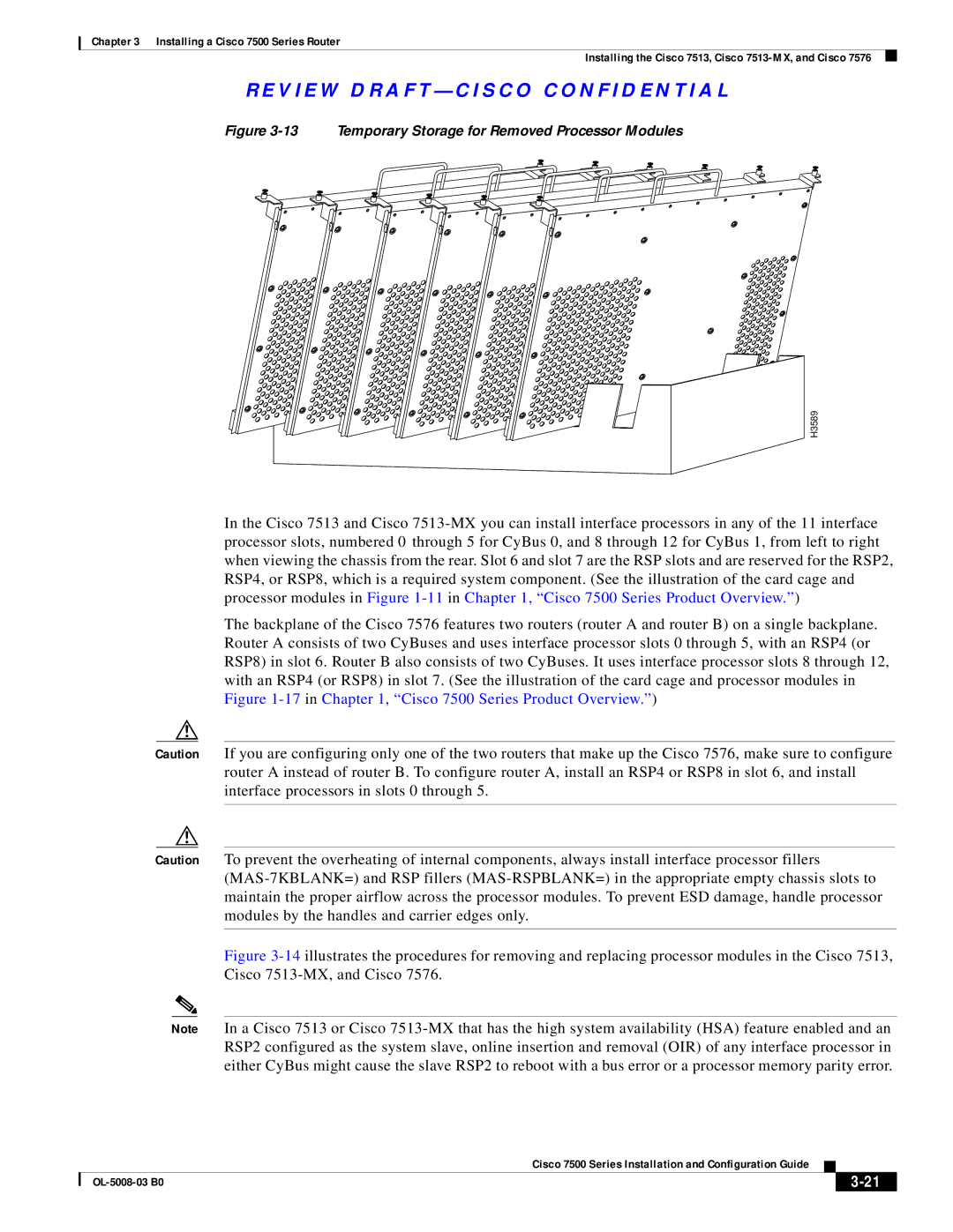
Figure 3-13 Temporary Storage for Removed Processor Modules
H3589
In the Cisco 7513 and Cisco
The backplane of the Cisco 7576 features two routers (router A and router B) on a single backplane. Router A consists of two CyBuses and uses interface processor slots 0 through 5, with an RSP4 (or RSP8) in slot 6. Router B also consists of two CyBuses. It uses interface processor slots 8 through 12, with an RSP4 (or RSP8) in slot 7. (See the illustration of the card cage and processor modules in Figure
Caution If you are configuring only one of the two routers that make up the Cisco 7576, make sure to configure router A instead of router B. To configure router A, install an RSP4 or RSP8 in slot 6, and install interface processors in slots 0 through 5.
Caution To prevent the overheating of internal components, always install interface processor fillers
Figure 3-14 illustrates the procedures for removing and replacing processor modules in the Cisco 7513, Cisco 7513-MX, and Cisco 7576.
Note In a Cisco 7513 or Cisco
|
| Cisco 7500 Series Installation and Configuration Guide |
|
| |
|
|
| |||
|
|
|
|
| |
|
|
|
| ||