Chapter 3 Installing a Cisco 7500 Series Router
Installing the Cisco 7513, Cisco
R E V I E W D R A F T — C I S CO CO N F I D E N T I A L
Warning Before working on a chassis or working near power supplies, unplug the power cord on AC units or disconnect the power at the circuit breaker on DC units.
Warning This unit might have more than one power cord. To reduce the risk of electric shock, disconnect the two power supply cords before servicing the unit.
Use this procedure to connect power to
Step 1 Turn off (O) the system power switch on the power supply you want to attach
Step 2 Remove the
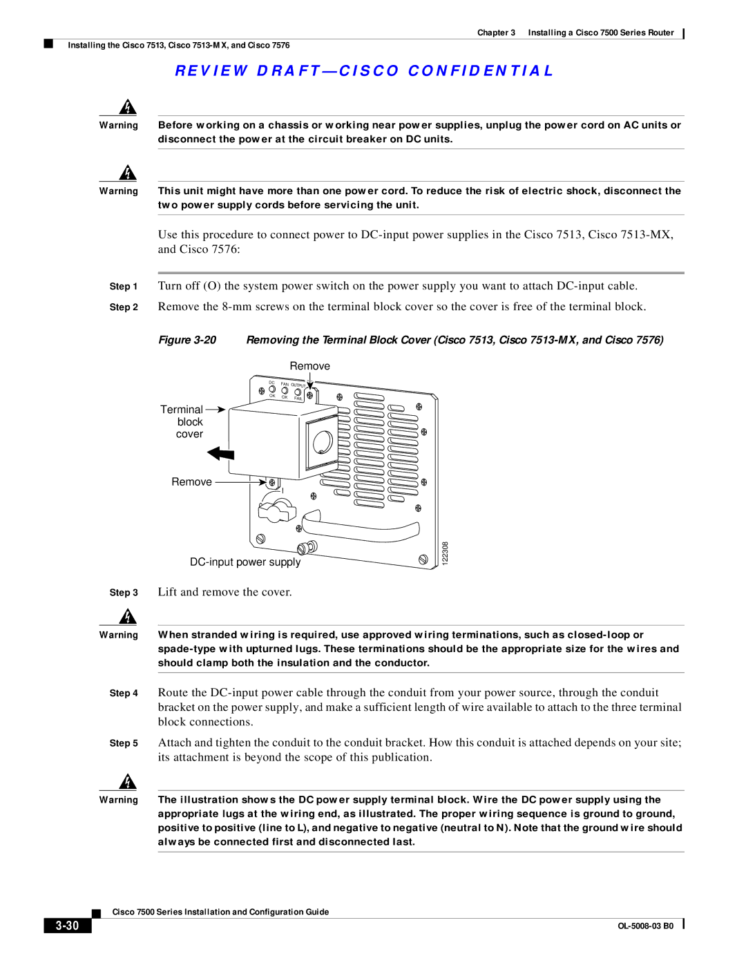
Figure 3-20 Removing the Terminal Block Cover (Cisco 7513, Cisco 7513-MX, and Cisco 7576)
Remove
DC | FAN | OUTPUT |
|
| |
OK | OK | FAIL |
|
|
Terminal ![]() block cover
block cover
Remove
![]() I
I
0
Step 3 Lift and remove the cover.
122308
Warning When stranded wiring is required, use approved wiring terminations, such as
Step 4 Route the
Step 5 Attach and tighten the conduit to the conduit bracket. How this conduit is attached depends on your site; its attachment is beyond the scope of this publication.
Warning The illustration shows the DC power supply terminal block. Wire the DC power supply using the appropriate lugs at the wiring end, as illustrated. The proper wiring sequence is ground to ground, positive to positive (line to L), and negative to negative (neutral to N). Note that the ground wire should always be connected first and disconnected last.
| Cisco 7500 Series Installation and Configuration Guide |