Chapter 6 Maintaining Your Cisco 7507 and Cisco
Maintenance Procedures for the Cisco 7507 and Cisco
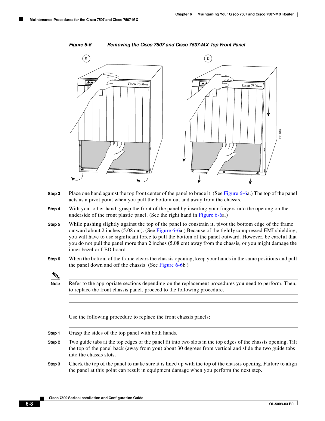
Figure 6-6 Removing the Cisco 7507 and Cisco 7507-MX Top Front Panel
a | b |
UPPER | LOWER | NORMAL |
|
|
POWER | POWER | UPPER | LOWER | NORMAL |
|
| POWER | ||
|
| POWER |
|
H3133
Step 3 Place one hand against the top front center of the panel to brace it. (See Figure
Step 4 With your other hand, grasp the front of the panel by inserting your fingers into the opening on the underside of the front plastic panel. (See the right hand in Figure
Step 5 While pushing slightly against the top of the panel to constrain it, pivot the bottom edge of the frame outward about 2 inches (5.08 cm). (See Figure
Step 6 When the bottom of the frame clears the chassis opening, keep your hands in the same positions and pull the panel down and off the chassis. (See Figure
Note Refer to the appropriate sections depending on the replacement procedures you need to perform. Then, to replace the front chassis panel, proceed to the following procedure.
Use the following procedure to replace the front chassis panels:
Step 1 Grasp the sides of the top panel with both hands.
Step 2 Two guide tabs at the top edges of the panel fit into two slots in the top edges of the chassis opening. Tilt the top of the panel back (away from you) about 30 degrees from vertical and slide the two guide tabs into the chassis slots.
Step 3 Check the top of the panel to make sure it is lined up with the top of the chassis opening. Failure to align the panel at this point can result in equipment damage when you perform the next step.
Cisco 7500 Series Installation and Configuration Guide
|
| |
|