Chapter 3 Installing a Cisco 7500 Series Router
Installing the Cisco 7513, Cisco
R E V I E W D R A F T — C I S CO CO N F I D E N T I A L
Step 4 Replace the card cage assembly. (See the procedure in the “Installing the Card Cage Assembly” section on page
Step 5 Replace the power supplies. (See the “Installing Cisco 7513, Cisco
Step 6 Replace the processor modules in the card cage. (See the procedure in Figure
This completes the procedure for installing the Cisco 7513, Cisco
Attaching the Cisco 7513, Cisco
Use the following procedure to install the
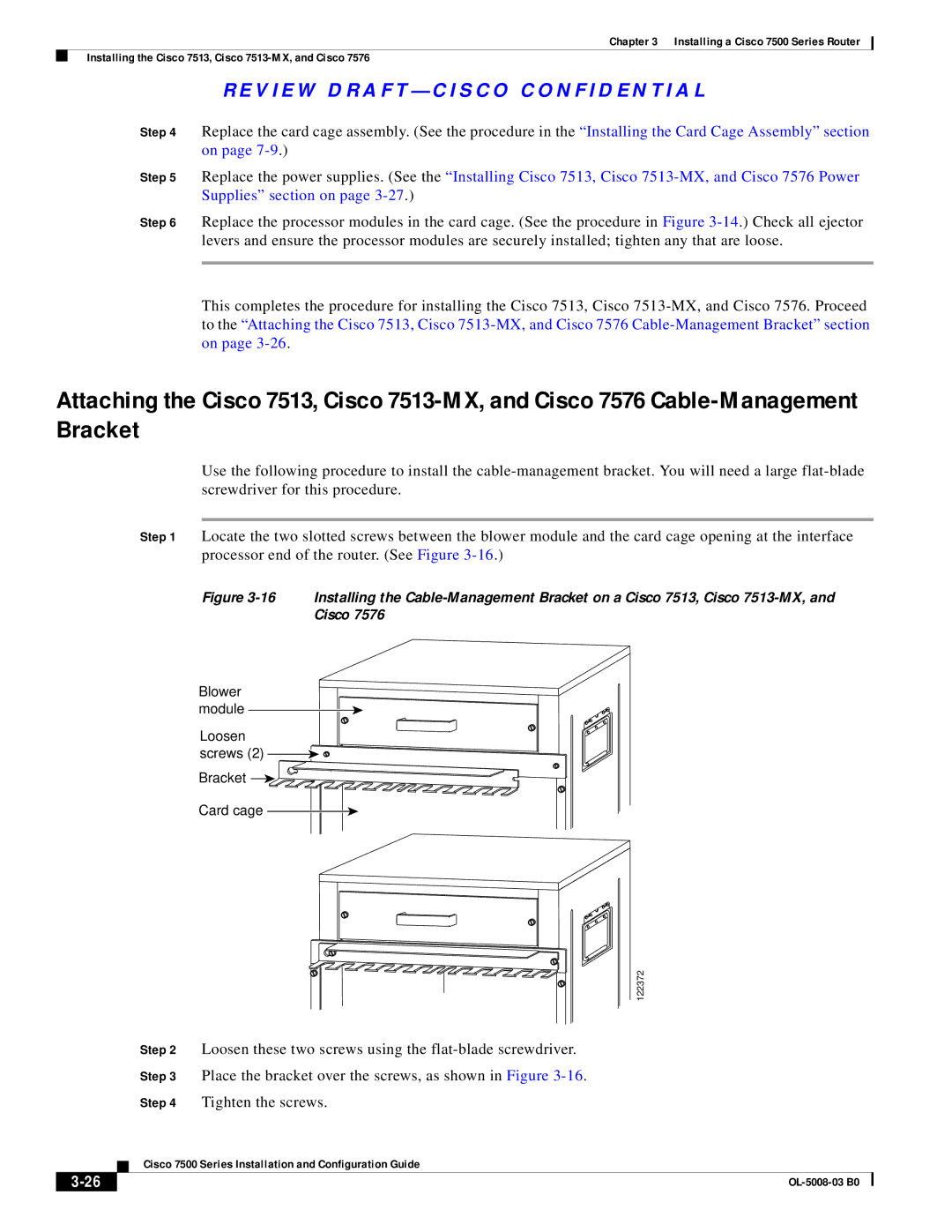
Step 1 Locate the two slotted screws between the blower module and the card cage opening at the interface processor end of the router. (See Figure
Figure 3-16 Installing the Cable-Management Bracket on a Cisco 7513, Cisco 7513-MX, and Cisco 7576
Blower module
Loosen
screws (2) 
 Bracket

Card cage
122372
Step 2 Loosen these two screws using the
Step 3 Place the bracket over the screws, as shown in Figure
Step 4 Tighten the screws.
| Cisco 7500 Series Installation and Configuration Guide |