Chapter 6 Maintaining Your Cisco 7507 and Cisco
Maintenance Procedures for the Cisco 7507 and Cisco
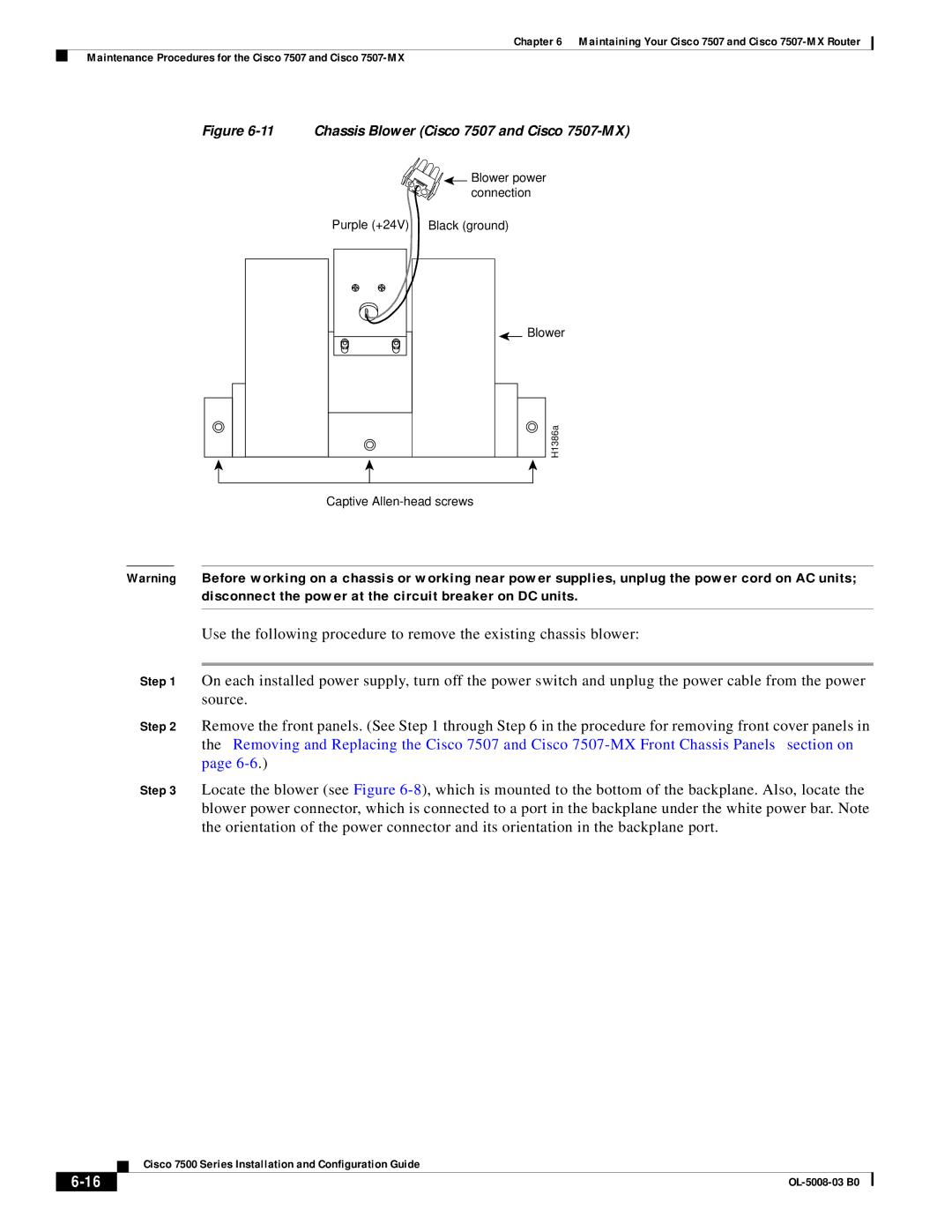
Figure 6-11 Chassis Blower (Cisco 7507 and Cisco 7507-MX)
![]() Blower power connection
Blower power connection
Purple (+24V) | Black (ground) |
![]() Blower
Blower
H1386a
Captive
Warning Before working on a chassis or working near power supplies, unplug the power cord on AC units; disconnect the power at the circuit breaker on DC units.
Use the following procedure to remove the existing chassis blower:
Step 1 On each installed power supply, turn off the power switch and unplug the power cable from the power source.
Step 2 Remove the front panels. (See Step 1 through Step 6 in the procedure for removing front cover panels in the “Removing and Replacing the Cisco 7507 and Cisco
Step 3 Locate the blower (see Figure
| Cisco 7500 Series Installation and Configuration Guide |
|