Chapter 6 Maintaining Your Cisco 7507 and Cisco
Maintenance Procedures for the Cisco 7507 and Cisco
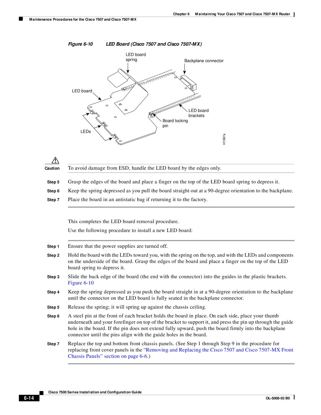
Figure 6-10 LED Board (Cisco 7507 and Cisco 7507-MX)
LED board |
|
spring | Backplane connector |
LED board
LED board
brackets
Board locking
pin
LEDs
H1387a
Caution To avoid damage from ESD, handle the LED board by the edges only.
Step 5 Grasp the edges of the board and place a finger on the top of the LED board spring to depress it.
Step 6 Keep the spring depressed as you pull the board straight out at a
Step 7 Place the board in an antistatic bag if returning it to the factory.
This completes the LED board removal procedure.
Use the following procedure to install a new LED board:
Step 1 Ensure that the power supplies are turned off.
Step 2 Hold the board with the LEDs toward you, with the spring on the top, and with the LEDs and components on the underside of the board. Grasp the edges of the board and place a finger on the top of the LED board spring to depress it.
Step 3 Slide the back edge of the board (the end with the connector) into the guides in the plastic brackets. Figure
Step 4 Keep the spring depressed as you push the board straight in at a
Step 5 Release the spring; it will spring up against the chassis ceiling.
Step 6 A steel pin at the front of each bracket holds the board in place. On each side, place your thumb underneath and your forefinger on top of the bracket to support it, and press the pin up through the guide hole in the board. If the pin does not extend fully upward, push the board firmly into the backplane connector until the pins align with the guide holes in the board.
Step 7 Replace the top and bottom front chassis panels. (See Step 1 through Step 9 in the procedure for replacing front cover panels in the “Removing and Replacing the Cisco 7507 and Cisco
| Cisco 7500 Series Installation and Configuration Guide |
|