Corporate Headquarters
Cisco 7500 Series Installation and Configuration Guide
Cisco 7500 Series Installation and Configuration Guide
Iii
N T E N T S
RSP Asynchronous Serial Ports-Console and Auxiliary
Installing a Cisco 7500 Series Router
Checking the Settings
Vii
Copying Files Between RSP Memory and a Flash Memory Card
Exchanging the Eeprom Devices
Viii
Bits 0-3 A-2
OL-5008-03 B0
Organization
Audience
Related Documentation
Chapter Title Description
Xii
Conventions
Convention Description
Xiii
Xiv
Waarschuwing Belangrijke Veiligheidsinstructies
Safety Warnings
Megjegyzés Õrizze MEG Ezeket AZ Utasításokat
Warnung Wichtige Sicherheitsanweisungen
Hinweis Bewahren SIE Diese Sicherheitsanweisungen AUF
Figyelem! Fontos Biztonsági Elõírások
Xvii
Aviso Instruções Importantes DE Segurança
Xviii
Restricted Area Warning
Xix
Obtaining Documentation
Ordering Documentation
Documentation Feedback
Obtaining Technical Assistance
Cisco.com
Xxi
Submitting a Service Request
Definitions of Service Request Severity
Cisco Technical Support Website
Xxii
Obtaining Additional Publications and Information
Cisco 7500 Series Product Overview
Terms and Acronyms
Cisco 7505 Overview
Cisco 7505 Front View
Cisco 7505 CyBus Backplane
Description Specification
Cisco 7505 System Specifications
Cisco 7507 Overview
Cisco 7507 Front View
Cisco 7507 Dual CyBus Backplane
Lower Power supply
Dual CyBus Backplane in the Cisco
Cisco 7507 System Specifications
Cisco 7507-MX Front View
Cisco 7507-MX Overview
Cisco 7507-MX Rear View
Cisco 7507-MX Dual CyBus Backplane
Dual CyBus Backplane in the Cisco 7507-MX
Cisco 7507-MX System Specifications
Cisco 7513 Overview
10 Cisco 7513 Front View
Receptacles
Cisco 7513 Dual CyBus Backplane
12 Dual CyBus Backplane in the Cisco
Cisco 7513 System Specifications
Cisco 7513-MX Overview
13 Cisco 7513-MX Front View
14 Cisco 7513-MX Rear View
Cisco 7513-MX Dual CyBus Backplane
15 Dual CyBus Backplane in the Cisco 7513-MX
Cisco 7513-MX System Specifications
Cisco 7576 Overview
16 Cisco 7576 Front View
Receptacles
Cisco 7576 Dual CyBus Backplane
18shows the details of the dual CyBus backplane
CyBus Slot Number Assignments
Identifying Cisco 7576 Independent Routers and CyBuses
Cisco 7576 System Specifications
Route Switch Processor Overview
RSP-Specific Hardware Features
RSP2-Cisco
Route Switch Processor RSP2
RSP4/4+-Cisco 7507, Cisco 7513, and Cisco
Type
Quantity Description Location
U13 U10
OL-5008-03 B0
Type Size Quantity Description Location
RSP8-Cisco 7507-MX and Cisco 7513-MX
U15 U12
Cisco 7500 Series Installation and Configuration Guide
SRAM3
Memd Data Asic
Type Size Quantity Description
Location See
Common RSP Hardware Features
RSP LEDs
Dram Description
Sram Description
RSP Flash Memory
RSP Asynchronous Serial Ports-Console and Auxiliary
RSP Eeprom
Signal Pin Direction Signal Description
Pin Signal Direction Signal Description
Female End DB-25 Pins Male End DB-25 Pins Description
AC-Input and DC-Input Power Supply Overview
24 AC-Input Power Supply Cisco
26 AC-Input Power Supply Cisco 7507 and Cisco 7507-MX
H3030
Chassis Interface Overview
Arbiter Overview
30 7500 Series Chassis Interface
Fan Tray and Blower Assembly Overview
Cisco 7507 and Cisco 7507-MX Blower Assembly
Cisco 7505 Fan Tray Assembly
32 Blower Assembly Cisco 7507 and Cisco 7507-MX
Interface Processor Overview
34 Blower Module Assembly Rear View
OL-5008-03 B0
System Software Overview
Tools and Parts You Need
Preparing for Installation
Safety with Electricity
Safety Recommendations
Chassis Lifting Guidelines
Lifting Safely Cisco 7507 Shown
Correct Way to Lift the Cisco 7513, Cisco 7513-MX, or Cisco
Preventing Electrostatic Discharge Damage
Cisco 7505 Power Considerations
AC-Input and DC-Input Power Guidelines
Cisco 7507 and Cisco 7507-MX Power Considerations
Page
Interference Considerations with Cabling
Plant Wiring Guidelines
Distance Limitations of Interface Cabling
Minimum Maximum
Cisco 7505 Airflow Considerations
Specifications Minimum Maximum
Chassis
Cisco 7507 and Cisco 7507-MX Airflow Considerations
General Equipment Rack Ventilation Considerations
Equipment Rack-Mounting Guidelines
Cisco 7505 Rack-Mount Considerations
Noninterface processor end
Cisco 7507 and Cisco 7507-MX Rack-Mount Considerations
Power supply/interface processor end
Cisco 7500 Series Installation and Configuration Guide
Panel end
Cisco 7500 Series Installation and Configuration Guide
Cisco 7500 Series Environmental Monitoring
Cisco 7505 Temperature and Voltage Thresholds
Cisco 7500 Series Temperature and Voltage Thresholds
Parameter Normal Low Critical Low Warning
Parameter Normal Critical Shutdown
Parameter Critical Normal
Parameter Normal High Warning High Critical Shutdown
Cisco 7500 Series Environmental Reports
Power supply 75C Restart 40C
Router# show env last
Cisco 7505 Environmental show Command Examples
Router# show env table
Airflow Temperature Measured
RSP3 Inlet 44C/111F 50C/122F
0123456 Dbus slots XX Inlet Hotpoint
At 32C
+24V 20.00 23.80V 28.00
Airflow
Cisco 7576 Environmental show Command Examples
LowCritical
Cisco 7500 Series General Installation Considerations
Installing a Cisco 7500 Series Router
V I E W D R a F T C I S CO CO N F I D E N T I a L
Providing a Ground Connection for the Chassis
Wire Grounding lug Chassis grounding receptacles Screws
Installation Flowchart Cisco
Installing the Cisco
V I E W D R a F T C I S CO CO N F I D E N T I a L
Remove a module as follows
Rack-Mounting the Cisco
Cisco 7505 Installation Considerations
Rack-mount the chassis as follows
Attaching the Cisco 7505 Cable-Management Brackets
Connecting Power to the Cisco 7505 DC-Input Power Supply
Removing the Terminal Block Cover and Attaching Power Cables
Insert power supplies Make external connections
Installing the Cisco 7507 and Cisco 7507-MX
V I E W D R a F T C I S CO CO N F I D E N T I a L
Stop
Installing Cisco 7507 and Cisco 7507-MX Power Supplies
Cisco 7507 and Cisco 7507-MX Installation Considerations
Captive installation screw
Step
Captive installation screws on terminal block cover
Terminal block cover
Installing the Cisco 7513, Cisco 7513-MX, and Cisco
Use Cisco 7513 and Cisco Unpacking Instructions
13 Temporary Storage for Removed Processor Modules
V I E W D R a F T C I S CO CO N F I D E N T I a L
Bottom ejector lever Remove a module as follows
Blower module weighs approximately 10 lb 4.55 kg
15 Lifting a Cisco 7513, Cisco 7513-MX, or Cisco
Blower module Loosen Screws 2 Bracket Card cage
V I E W D R a F T C I S CO CO N F I D E N T I a L
Captive screws
19 Power Supply Blank Cisco 7513, Cisco 7513-MX, and Cisco
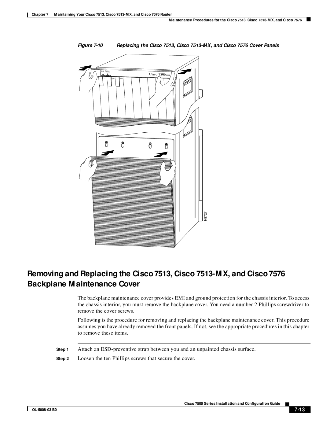
Lift and remove the cover
DC-input power supply With the terminal block Cover removed
Connecting a Console Terminal to the RSP
Connecting to the Auxiliary Port
Making Cable Connections to the RSP
What Do I Do Now?
Using the Y-Cables for Console and Auxiliary Connections
V I E W D R a F T C I S CO CO N F I D E N T I a L
Performing a Basic Configuration of the System
Starting the System and Observing Initial Conditions
Performing a Basic Configuration of the System
Bit Number Hexadecimal Meaning
Configuring the Software Configuration Register
Boot Field Meaning
Configuration Register Bit Meanings
Bit Address net host
Action/Filename Bit
Baud Bit
Changing Configuration Register Settings
Using the Enable Secret and the Enable Password
Booting the Cisco 7500 Series Router for the First Time
Recovering a Lost Password
Initialize the router by entering the i command as follows
Performing a Basic Configuration Using AutoInstall
Configuring the Cisco 7500 Series System
Configuring the Global Parameters
OK?
Enter yes or no to accept or refuse Snmp management
Configuring an Ethernet Interface
Configuring Interfaces
Configuring a Synchronous Serial Interface
Interface Ethernet0/0
Performing a Basic Configuration Using Configuration Mode
Checking the Settings
Implementing Other Configuration Tasks
Installing and Removing a Flash Memory Card in an RSP
Using the Flash Memory Cards in the RSPs
OL-5008-03 B0
Installing and Removing a Flash Memory Card RSP2
Installing and Removing a Flash Memory Card RSP4/4+ and RSP8
Router# format slot0
Formatting a Flash Memory Card
Copying Files to Flash Memory
Making a Flash Memory Card Image Bootable
Additional Commands Associated with Flash Memory
Enabling Booting from Flash Memory
Copying a Bootable Image into a Flash Memory Card
Additional Procedures Associated with Flash Memory Cards
Router# copy tftpnew.image slot0new.image
Copying Bootable Images Between Flash Memory Cards
Router# copy slot1image.new slot0image.new
Copying Files Between RSP Memory and a Flash Memory Card
Router# copy startup-config slot0myfile2
Router# copy running-config slot0myfile2
Recovering from Locked Blocks in Flash Memory Cards
If You Need More Configuration Information
OL-5008-03 B0
OL-5008-03 B0
Maintaining Your Cisco 7505 Router
Overview of Maintenance Procedures for the Cisco
Tools Required for Maintenance Procedures
Removing and Replacing the Cisco 7505 Cover Panel
Maintenance Procedures for the Cisco
Removing and Replacing the Cisco 7505 Cover Panel
Replacing the Cisco 7505 Fan Tray
Removing and Replacing the Cisco 7505 Fan Tray
Fan Tray Tracks and Guides in the Cisco
Removing and Replacing the Cisco 7505 Power Harness Cover
Removing the Cisco 7505 Power Harness Cover
Removing and Replacing the Cisco 7505 Backplane Cover
Removing and Replacing the Cisco 7505 Backplane Cover
7500 Series Chassis Interface
Removing and Replacing the Chassis Interface in the Cisco
Removing and Replacing the CI Cisco
Cisco 7505 AC-Input Power Supply-Interface Processor End
Removing and Replacing the Cisco 7505 Power Supply
Removing and Replacing the Cisco 7505 Power Supply
OL-5008-03 B0
OL-5008-03 B0
Maintaining Your Cisco 7507 and Cisco 7507-MX Router
Tools Required for Maintenance Procedures
Breaker in the OFF position
Maintenance Procedures for the Cisco 7507 and Cisco 7507-MX
Removing Cisco 7507 and Cisco 7507-MX Power Supplies
Should clamp both the insulation and the conductor
H2530
Fail Power
Cisco 7500 Series Installation and Configuration Guide
Removing the Cisco 7507 and Cisco 7507-MX Bottom Front Panel
Removing the Cisco 7507 and Cisco 7507-MX Top Front Panel
Replacing the Cisco 7507 and Cisco 7507-MX Front Panels
OL-5008-03 B0
Cisco 7507 and Cisco 7507-MX Internal Chassis Components
Replacing Cisco 7507 and Cisco 7507-MX Internal Components
7500 Series Chassis Interface
OL-5008-03 B0
10 LED Board Cisco 7507 and Cisco 7507-MX
OL-5008-03 B0
11 Chassis Blower Cisco 7507 and Cisco 7507-MX
12 Blower Power Connection Cisco 7507 and Cisco 7507-MX
Cisco 7500 Series Installation and Configuration Guide
OL-5008-03 B0
OL-5008-03 B0
A P T E R
Tools Required for Maintenance Procedures
Page
H5265
Power Supply Blank Cisco 7513, Cisco 7513-MX, and Cisco
Removing the Card Cage Assembly
Captive screw
Exchanging the Eeprom Devices
Eeprom B
Installing the Card Cage Assembly
Installing the Card Cage Assembly
Blower module
Cisco 7500 Series Installation and Configuration Guide
H9728
H9727
Loosen these screws
12 Cisco 7500 Series Chassis Interface
Dual arbiters Chassis B interfaces
H3099
16 Removing and Replacing the Cisco 7576 CI Cutaway View
OL-5008-03 B0
OL-5008-03 B0
Troubleshooting a Cisco 7500 Series Router
Troubleshooting Overview
Problem Solving with Cisco 7500 Series Subsystems
Identifying Cisco 7505 Startup Problems
Troubleshooting Guidelines for the Cisco
ENVM-2-FAN Fan array has failed, shutdown in 2 minutes
Cisco Systems, Inc Tasman Drive San Jose, CA
Troubleshooting the Cisco 7505 Cooling Subsystem
Troubleshooting the Cisco 7505 Power Subsystem
ENVM-2-FAN Fan array has failed, shutdown in 2 minutes
Identifying Cisco 7507 and Cisco 7507-MX Startup Problems
OL-5008-03 B0
Troubleshooting a Cisco 7500 Series Router
Subsystem Yes Fans
V I E W D R a F T C I S CO CO N F I D E N T I a L
ENVM-2-FAN Fan has failed, shutdown in 2 minutes
V I E W D R a F T C I S CO CO N F I D E N T I a L
V I E W D R a F T C I S CO CO N F I D E N T I a L
Troubleshooting Blower Operation
Troubleshooting the RSP
Troubleshooting the Cisco 7500 Series Processor Subsystem
Using Cisco 7500 Series System LEDs
Troubleshooting the Interface Processors
Using the Front-Panel System LEDs
Cisco 7513, Cisco 7513-MX, and Cisco 7576 LEDs
Cisco 7507 and Cisco 7507-MX LEDs
RSP2 LEDs-Cisco 7500 Series
Using the RSP LEDs
RSP4 and RSP8 LEDs Partial Front Panel, Horizontal View
RSP4 and RSP8 LEDs-Cisco 7500 Series
Using the Power Supply LEDs
Cisco 7505 Power Supply LED
Cisco 7507 and Cisco 7507-MX Power Supply LEDs
AC-Input Power Supply LEDs Cisco 7507 and Cisco 7507-MX
Cisco 7513, Cisco 7513-MX, and Cisco 7576 Power Supply LEDs
Additional Reference Information for Troubleshooting
Upgrading or Replacing Dram SIMMs on the RSP2
Replacing Dram on the Route Switch Processor
MEM-RSP-24M
Quantity Dram Bank Total Dram Product Numbers
Releasing the RSP2 Simm Spring Clips
Removing RSP2 SIMMs
Handling an RSP2 Simm
Installing New RSP2 SIMMs
Upgrading or Replacing Dram DIMMs on the RSP4 and RSP8
RSP4 Dram Dimm Locations
RSP8 Dram Dimm Locations
Quantity Totals Product Numbers
Removing RSP4 and RSP8 DIMMs
Handling an RSP4 or RSP8 Dimm
Installing New RSP4 or RSP8 DIMMs
Installing an RSP4 or RSP8 Dram Dimm in the Socket
OL-5008-03 B0
Bit No Hex Meaning
Configuration Bit Meanings
Bits
Action/File Name Bit
Bit
Bit 10 and Bit
Bit 11 and Bit
Bit IP Address net host
Router# show version
Setting the Configuration Register While Running Cisco IOS
Info? y/n Change
OL-5008-03 B0
IN-1
Numerics
IN-2
IN-3
IN-4
RSP4
IN-5
IN-6
IN-7
Configuration
IN-8
RSP2 RSP4
IN-9
Exec
IN-10
Cisco 7507 and Cisco 7507-MX 3-14 to 3-19,6-3 to
IN-11
DC OK
IN-12
PFC
Service Site guidelines
IN-14
IN-15
RSP
IN-16
Snmp
IN-17
CPU RSP2 RSP4
IN-18
IN-19
 H9727
H9727