Chapter 7 Maintaining Your Cisco 7513, Cisco
Maintenance Procedures for the Cisco 7513, Cisco
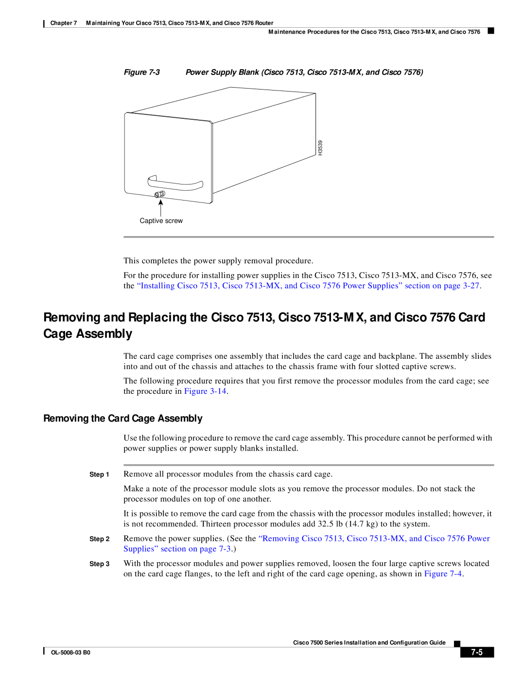
Figure 7-3 Power Supply Blank (Cisco 7513, Cisco 7513-MX, and Cisco 7576)
H3539
Captive screw
This completes the power supply removal procedure.
For the procedure for installing power supplies in the Cisco 7513, Cisco
Removing and Replacing the Cisco 7513, Cisco
The card cage comprises one assembly that includes the card cage and backplane. The assembly slides into and out of the chassis and attaches to the chassis frame with four slotted captive screws.
The following procedure requires that you first remove the processor modules from the card cage; see the procedure in Figure
Removing the Card Cage Assembly
Use the following procedure to remove the card cage assembly. This procedure cannot be performed with power supplies or power supply blanks installed.
Step 1 Remove all processor modules from the chassis card cage.
Make a note of the processor module slots as you remove the processor modules. Do not stack the processor modules on top of one another.
It is possible to remove the card cage from the chassis with the processor modules installed; however, it is not recommended. Thirteen processor modules add 32.5 lb (14.7 kg) to the system.
Step 2 Remove the power supplies. (See the “Removing Cisco 7513, Cisco
Step 3 With the processor modules and power supplies removed, loosen the four large captive screws located on the card cage flanges, to the left and right of the card cage opening, as shown in Figure
Cisco 7500 Series Installation and Configuration Guide
|
|
| |
|
|