Chapter 7 Maintaining Your Cisco 7513, Cisco
Maintenance Procedures for the Cisco 7513, Cisco
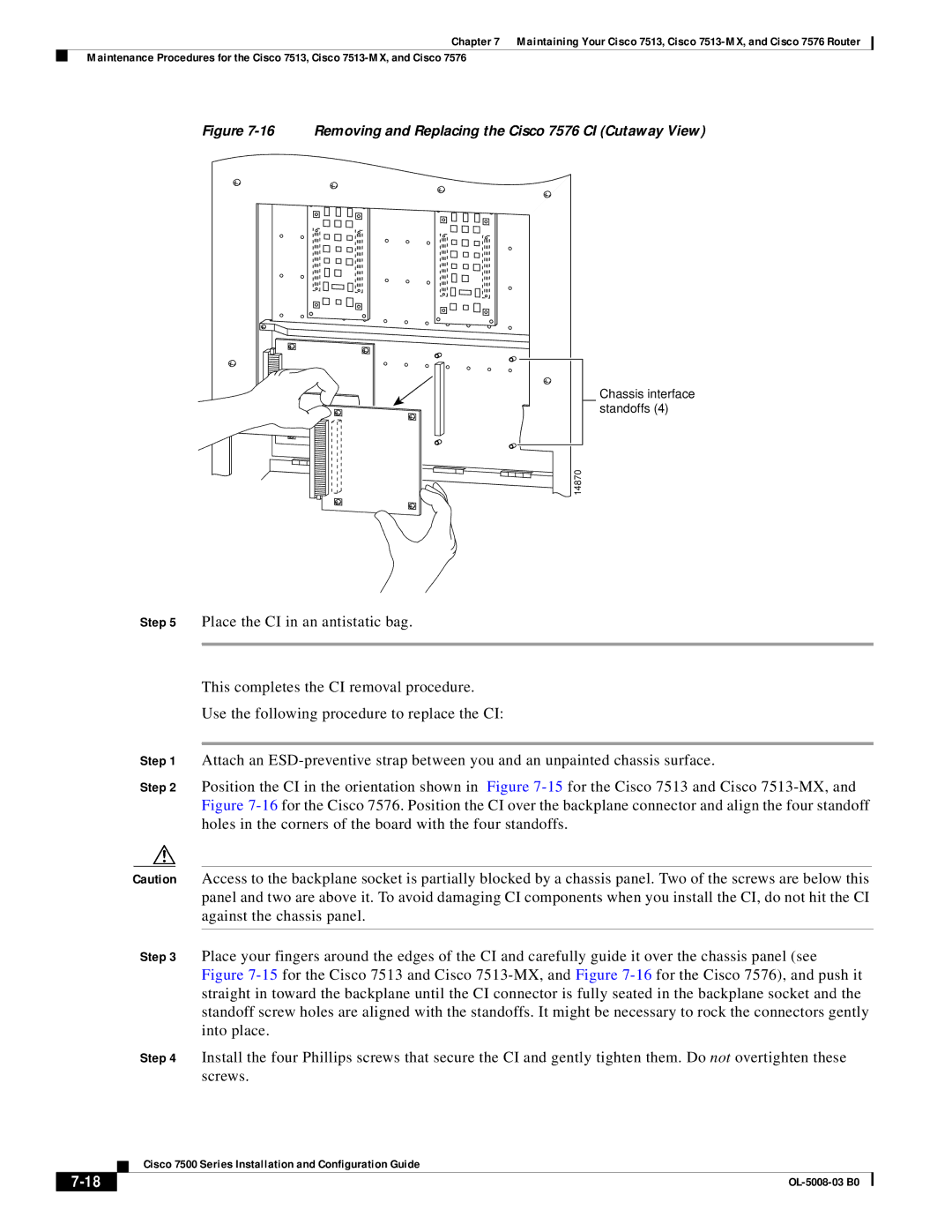
Figure 7-16 Removing and Replacing the Cisco 7576 CI (Cutaway View)
Chassis interface standoffs (4)
14870
Step 5 Place the CI in an antistatic bag.
This completes the CI removal procedure.
Use the following procedure to replace the CI:
Step 1 Attach an
Step 2 Position the CI in the orientation shown in Figure
Caution Access to the backplane socket is partially blocked by a chassis panel. Two of the screws are below this panel and two are above it. To avoid damaging CI components when you install the CI, do not hit the CI against the chassis panel.
Step 3 Place your fingers around the edges of the CI and carefully guide it over the chassis panel (see Figure
Step 4 Install the four Phillips screws that secure the CI and gently tighten them. Do not overtighten these screws.
| Cisco 7500 Series Installation and Configuration Guide |
|