Chapter 7 Maintaining Your Cisco 7513, Cisco
Maintenance Procedures for the Cisco 7513, Cisco
Removing and Replacing the Cisco 7513, Cisco
In the Cisco 7513, Cisco
Warning Although the system should not be operating when you remove the blower module, it is not necessary to turn OFF system power before removing the blower module. However, with the system power ON and the blower module removed, high current is exposed on the blower module power connector at the backplane; do not insert conductive items into the empty blower module opening. After an operating blower module is removed, the blower impeller blades will continue to spin for approximately two minutes; do not insert anything into the module’s vent holes while the impeller is spinning.
Caution With chassis power on and the blower module removed, no cooling air is circulating through the system. Replace the blower module before the system overheats. The system will shut down approximately 2 minutes after reaching the shutdown temperature threshold.
Use the following procedure to remove and replace the blower module:
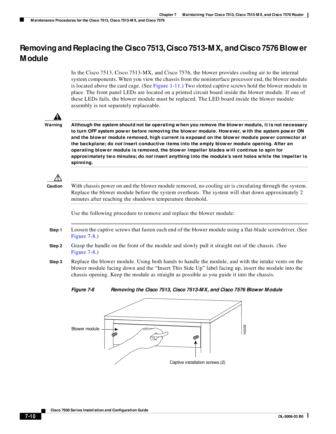
Step 1 Loosen the captive screws that fasten each end of the blower module using a
Step 2 Grasp the handle on the front of the module and slowly pull it straight out of the chassis. (See Figure
Step 3 Replace the blower module. Using both hands to handle the module, and with the intake vents on the blower module facing down and the “Insert This Side Up” label facing up, insert the module into the chassis opening. Keep the module as straight as possible as you guide it into the chassis.
Figure 7-8 Removing the Cisco 7513, Cisco 7513-MX, and Cisco 7576 Blower Module
Blower module 
H3038
Captive installation screws (2)
| Cisco 7500 Series Installation and Configuration Guide |
|