Chapter 6 Maintaining Your Cisco 7507 and Cisco
Maintenance Procedures for the Cisco 7507 and Cisco
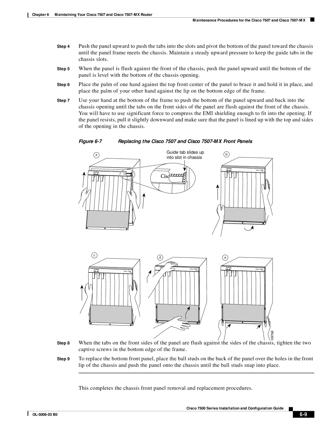
Step 4 Push the panel upward to push the tabs into the slots and pivot the bottom of the panel toward the chassis until the panel frame meets the chassis. Maintain a steady upward pressure to keep the guide tabs in the chassis slots.
Step 5 When the panel is flush against the front of the chassis, push the panel upward until the bottom of the panel is level with the bottom of the chassis opening.
Step 6 Place the palm of one hand against the top front center of the panel to brace it and hold it in place, and place the palm of your other hand against the lip on the bottom edge of the frame.
Step 7 Use your hand at the bottom of the frame to push the bottom of the panel upward and back into the chassis opening until the tabs on the front sides of the panel are flush against the front of the chassis. You will have to use significant force to compress the EMI shielding enough to fit into the opening. If the panel resists, pull it slightly downward and make sure that the panel is lined up with the top and sides of the opening in the chassis.
Figure 6-7 Replacing the Cisco 7507 and Cisco 7507-MX Front Panels
a | Guide tab slides up | b | |
into slot in chassis | |||
|
|
SERIES
c | e |
d |
SERIES | SERIES |
SERIES
H9768 |
Step 8 When the tabs on the front sides of the panel are flush against the sides of the chassis, tighten the two captive screws in the bottom edge of the frame.
Step 9 To replace the bottom front panel, place the ball studs on the back of the panel over the holes in the front lip of the chassis and push the panel onto the chassis until the ball studs snap into place.
This completes the chassis front panel removal and replacement procedures.
Cisco 7500 Series Installation and Configuration Guide
|
|
| |
|
|