Chapter 5 Maintaining Your Cisco 7505 Router
Maintenance Procedures for the Cisco 7505
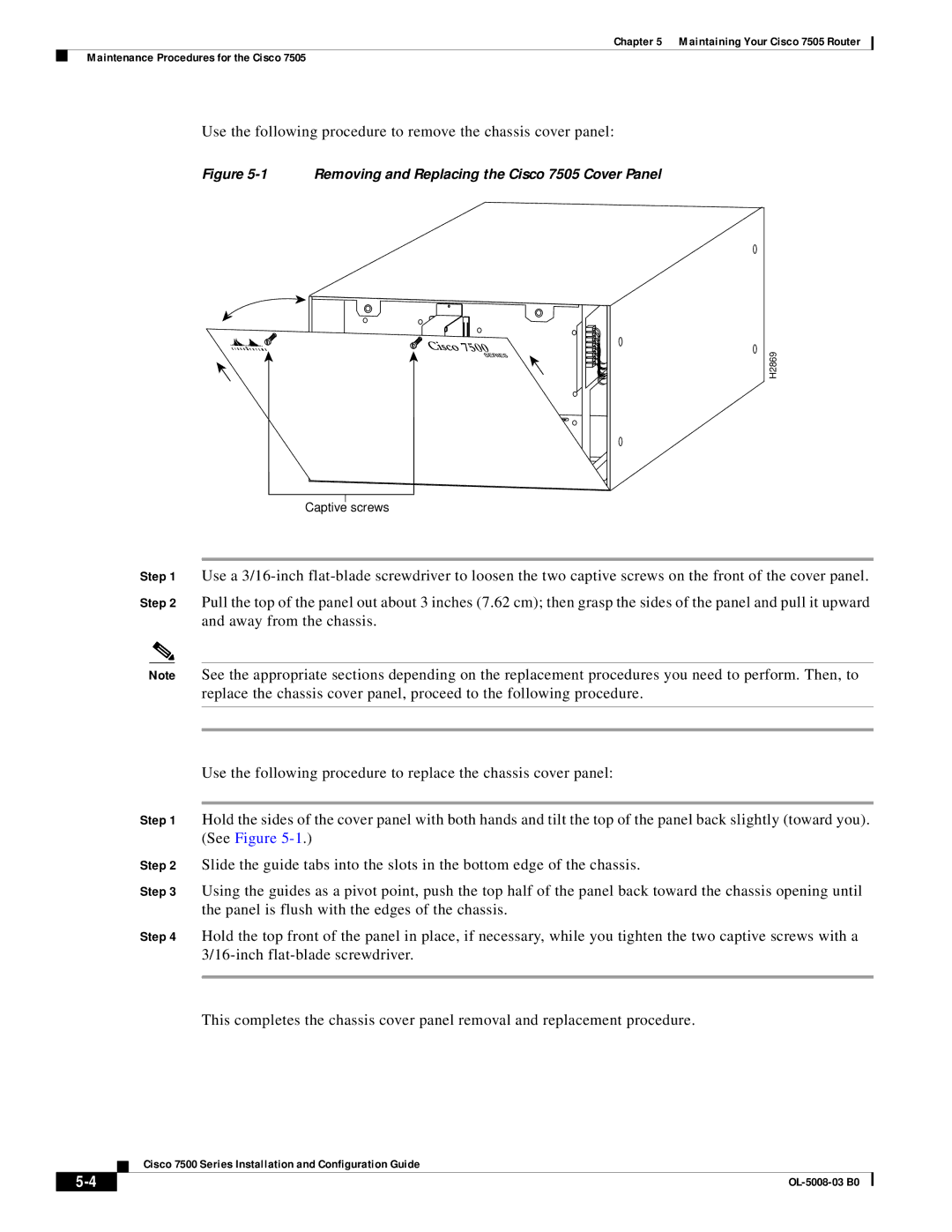
Use the following procedure to remove the chassis cover panel:
Figure 5-1 Removing and Replacing the Cisco 7505 Cover Panel
H2869
Captive screws
Step 1 Use a
Step 2 Pull the top of the panel out about 3 inches (7.62 cm); then grasp the sides of the panel and pull it upward and away from the chassis.
Note See the appropriate sections depending on the replacement procedures you need to perform. Then, to replace the chassis cover panel, proceed to the following procedure.
Use the following procedure to replace the chassis cover panel:
Step 1 Hold the sides of the cover panel with both hands and tilt the top of the panel back slightly (toward you). (See Figure
Step 2 Slide the guide tabs into the slots in the bottom edge of the chassis.
Step 3 Using the guides as a pivot point, push the top half of the panel back toward the chassis opening until the panel is flush with the edges of the chassis.
Step 4 Hold the top front of the panel in place, if necessary, while you tighten the two captive screws with a
This completes the chassis cover panel removal and replacement procedure.
Cisco 7500 Series Installation and Configuration Guide
|
| |
|