Chapter 2 Preparing for Installation
Site Environment, Chassis Temperature, and Airflow Guidelines
Cisco 7507 and Cisco 7507-MX Airflow Considerations
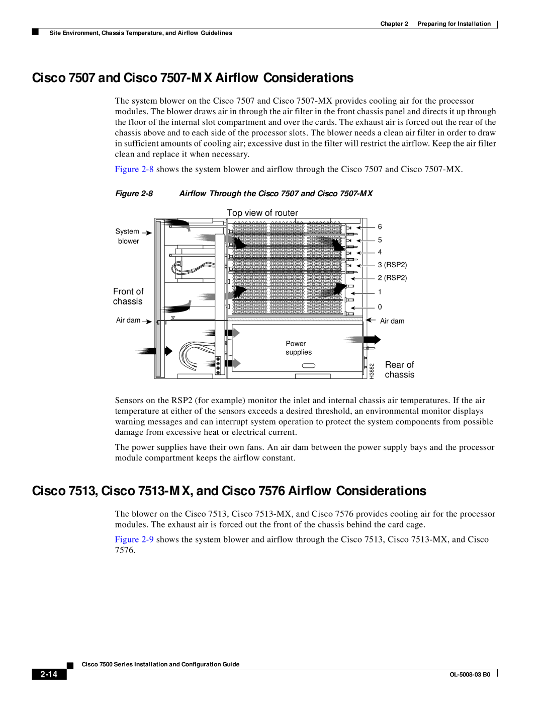
The system blower on the Cisco 7507 and Cisco
Figure 2-8 shows the system blower and airflow through the Cisco 7507 and Cisco 7507-MX.
Figure 2-8 Airflow Through the Cisco 7507 and Cisco 7507-MX
Top view of router
System | 6 |
| |
blower | 5 |
| 4 |
| 3 (RSP2) |
| 2 (RSP2) |
Front of | 1 |
chassis | 0 |
| |
Air dam | Air dam |
Power |
|
supplies |
|
H3882 | Rear of |
chassis |
Sensors on the RSP2 (for example) monitor the inlet and internal chassis air temperatures. If the air temperature at either of the sensors exceeds a desired threshold, an environmental monitor displays warning messages and can interrupt system operation to protect the system components from possible damage from excessive heat or electrical current.
The power supplies have their own fans. An air dam between the power supply bays and the processor module compartment keeps the airflow constant.
Cisco 7513, Cisco
The blower on the Cisco 7513, Cisco
Figure 2-9 shows the system blower and airflow through the Cisco 7513, Cisco 7513-MX, and Cisco 7576.
Cisco 7500 Series Installation and Configuration Guide
|
| |
|
