HDP5000 High Definition Card Printer/Encoder User Guide Rev
Part Number L000950
Revision Control Date Document Title Number
Mailsales@fargo.com
Table of Contents
Accessory Procedures
Card Lamination Module
Printer Adjustments
Toolbox
Fargo Workbench Printer Utility
How to use the guide
Manual Description
Safety Messages review carefully
Reviewing the HDP5000 Boot-up Sequence
HDP5000 Process Flow in table format
Step Process
Reviewing the HDP5000 Sequence of Operations
Reviewing HDP5000 Card Printer Sequence of Operations
Reviewing the Lamination Module Boot-up Sequence
Reviewing the Lamination Module Sequence of Operations
Specifications
Modules
Introduction
Reviewing the HDP5000 Printer Overview table
HDP5000 100
Reviewing the HDP5000 Package
Reviewing the HDP5000 front
Reviewing the HDP5000 Card Printer
Display HDP5000 Printer with attached Output Hopper
Term Description
Regulatory Compliances
Agency Listings
File Number E145118
FCC Rules
Environmental Protection China-RoHS
Technical Specifications
Compositions Card Cleaning
HDP5000 and HDP5000-LC
Card Sizes
Technical Specifications
Adjustments
HDP5000 and HDP5000-LC See Card tab under Printer
Technical Specifications
HDP5000 + Dual-Sided Module 11.50H x 17.50W x 9.25D
HDP5000 + Single-Sided Lam Module 12.75H x 25W
HDP5000 + Dual-Sided Module + Dual-Sided Lam Module
HDP5000 and HDP5000-LC
16MB RAM
HDP5000/HDP5000-LC
Print Ribbon
HDP5000 and HDP5000-LC prints or images
HDP5000 and HDP5000-LC see note below
Windows 2000 / XP / Server
HDP5000 with Card Lamination Module
HDP5000 + Dual-Sided Module 22 lbs. / 10 kg
HDP5000 + Single-Sided Lam Module 28 lbs. / 12.7 kg
36 lbs. / 16.4 kg
Functional Specifications
Function Description
Component Description
Printer Components LCD and Softkey Control Pad
Pause
Cancel
Printer Components LCD and Softkey Control Pad
Resume
Printer Components Print Ribbons
Printer Components Blank Cards
Type Description
Printer Components Blank Cards
Printer Components Card Input and Output Hoppers
Printer Components Card Output Hopper and Reject Hopper
Printer Unit Reviewing the Card Lamination Module
Printer Components Transfer Roller
Thermal Transfer Film The Thermal
Reviewing the Overlaminates
Term Description Cross Reference
PolyGuard Overlaminate PolyGuard
Reviewing the CR-80 Patch Size
Reviewing the Overlaminate Design
Performing repair procedures, unless otherwise specified
Symbol as shown to the left
Before performing an operation preceded by this symbol
Hands, as well as thoroughly clean hands to remove oil
Inspection HDP5000
Time Requirement
System Requirements
Unpacking the Printer
Display a See the HDP5000 Printer Installation Guide
Unpacking the Printer
Display B See the HDP5000 Printer Installation Guide
Choosing a Good Location
About Moisture Condensation
Printer Loading Procedures
Step Procedure
Loading the Print Ribbon
Loading the Print Ribbon
Tighten the Print Ribbon
Loading the Print Ribbon
Loading the Clear HDP Transfer Film
Loading the Clear HDP Transfer Film
Tighten the HDP Film
Loading the Clear HDP Transfer Film
Inserting the Card Cleaning Roller
Inserting the Card Cleaning Roller
Remove the protective sleeve from the Card Cleaning Roller
Insert the Card Cleaning Roller into the card input area
Loading the Overlaminate
Loading the Overlaminate
Tighten the Lamination Rolls
Close the Lamination Module Front Cover
Loading the Blank Cards
Load the blank cards into the Card Cartridge, as shown below
Loading the Blank Cards
Connecting Power to HDP5000 Printer and Lamination Module
Connecting Power to HDP5000 Printer and Lamination Module
Connecting Power to HDP5000 Printer and Lamination Module
Printer Driver Installation Procedures
Installing the HDP5000 Printer Driver
Installing the HDP5000 Printer Driver
Click on the Next button to continue with the installation
Read the License Agreement. Select the I accept the terms
License agreement option
Select Local to install a USB Printer
Select Network and enter an IP Address for the Printer
Click on the Next button to begin the installation
Wait during the installation
Step Procedure Applies to USB Printer installation
Connect the USB cable to both the PC and the Printer
Installing the HDP5000 Printer Driver
Click the Finish button Reboot your computer
You have completed this procedure
Windows XP or Printers Windows
Open the Driver settings
Printing a Test Print Image
Will bring up the HDP5000 Printing Preferences window
Printing a Test Print Image
To prevent equipment or media damage, refer to
Using the Security Lock Slot on the HDP5000
Using the Security Lock Slot on the HDP5000
Removing the Output Side Upgrade Cover
Estimated Repair Time 1 minute Step Procedure
Installing the Flipper Module Accessory
Estimated Repair Time 20 minutes Step Procedure
Flipper Module Accessory
Installing the Lamination Module Accessory
Estimated Repair Time 10 minutes Step Procedure
Installing the Lamination Module Accessory
General Troubleshooting
LCD Messages
Safety Messages review carefully
Troubleshooting LCD and Printer Error Message Tables
How to use the LCD Error Message Table example provided
Troubleshooting with the LCD Error Message Table
LCD Error Message Cause Solution
Press Resume or Cancel
Troubleshooting with the LCD Error Message Table
See Cleaning the Printer
Troubleshooting with the LCD Error Message Table
Troubleshooting with the LCD Error Message Table
Troubleshooting with the LCD Error Message Table
Troubleshooting with the LCD Error Message Table
Troubleshooting with the LCD Error Message Table
Troubleshooting with the LCD Error Message Table
Troubleshooting with the LCD Error Message Table
Troubleshooting with the LCD Error Message Table
Troubleshooting with the LCD Error Message Table
Cancel Print button or
Cancel button located on
Film Rfid tag is bad
Print
Cancel
Troubleshooting with the LCD Error Message Table
Troubleshooting with the LCD Error Message Table
See Resolving
Troubleshooting with the Printer Error Message Table
Printer Error Cause Solution Message
On Cancel Print
Troubleshooting with the Printer Error Message Table
Troubleshooting with the Printer Error Message Table
Troubleshooting with the Printer Error Message Table
Troubleshooting with the Printer Error Message Table
Troubleshooting with the Printer Error Message Table
Troubleshooting with the Printer Error Message Table
Troubleshooting with the Printer Error Message Table
Troubleshooting with the Printer Error Message Table
Cancel Print
Button to continue
Power and press the Resume
Cord is properly connected, cycle
On the Printer
Cancel Print button or the Cancel
Troubleshooting with the Printer Error Message Table
Troubleshooting with the Printer Error Message Table
Restricted USE ONLYFargo Electronics, Inc
Communications Errors
Resolving the Communication Errors
Resolving the Communication Errors
Printing a Test Image
Reviewing the Alignment Self Test Card
Reviewing the Color Bars Self Test
Reviewing the Device Settings Self Test
Reviewing the Ymck Self Test
Reviewing the Magnetic Self Test
Reviewing the Resin Self Test
Ethernet Option Section
Technical Specification Ethernet Option
Here are the system requirements for Ethernet
Function Requirement
Feature Description
Functional Specification Ethernet Option
Fargo Ethernet option includes these features
Provides an Snmp agent that supports MIB-II
Reviewing the Network Management Interface
Reviewing the Print Server
Reviewing the Web Page Server
Reviewing the Telnet Server
Initiating a Telnet Session
Interface Description
Reviewing the Telnet Command Table
Telnet Command Command Purpose Command Format
Reviewing the Telnet Command Table
Command Purpose Command Format
Newname
Password
Reviewing the Telnet Command Table
Ethernet Web Pages Standard Procedures
Reviewing Web page security
Logging
Accessing the Home
Reviewing the Home
This section provides a display of the HDP5000 Home
Reviewing the Home Page Categories and Fields table
Category Field Purpose
Configuring the Network Settings
Accessing the Network Settings
Select the Network link from any web page of the Printer
Reviewing the Current Settings
Reviewing the Interface
Switching to the Automatic IP Address Mode
Changing to the Static IP Address Mode
Changing to the static IP address mode
See the Reviewing Web page security procedure
Using the Clear Changes button
Using the Media Information
Using the TCP/IP
Using the TCP/IP
See the Using the TCP/IP page procedure
Using the Printer
Reviewing the Printer
See the previous page for descriptions of the fields
Using the System Log
Changing the Log Name
Selecting the Log Type
Step Procedure No event logging
Selecting the Log Destination
Specify one destination for the log
Setting up Email Event logging
Step Procedure Specify email logging
Specifying UDP Event logging
Specifying UDP Event logging
Select the TCP Connection radio button
Specifying TCP Event logging
Select the System Log link
Accepted after you have successfully logged
Specifying TCP Event logging
Using the Administration pages
Using the System Information
Location textbox
Using the System Information
Label textbox
Contact textbox
Changing the Root Password
Using the Reboot pages
Rebooting the Printer
Upgrading the Main Firmware
Upgrading the Main Firmware HDP5000 only
Upgrading the Main Firmware HDP5000 only
Select Reboot when requested. See Display B below
Select the Browse button. See Display a below
Navigate to and select the appropriate file to upload
Using the Print Path
Using the Print Path
Reviewing the HDP5000 LED Table
Accessing the Ethernet Status LEDs
Using the Help
Flash Rate Indicates Green LED
Step Procedure
Step Procedure
Changing the HDP5000 LCD Network Settings
Restoring the Factory Settings for Ethernet
Resetting the HDP5000 settings
Accessing the Network Setup Menu
Changing the Dhcp Setting
Changing the Aneg setting
Network Settings menu Options -Menu Next Network Settings
Resetting Passwords
Saving addresses
Accessing the HDP5000 IP Address
Follow this procedure
Follow the Printing a test page procedure
Troubleshooting procedures
Command procedure
Must match the model of the Printer
Verifying the Printer Connection
Verifying the Printer IP address
Step
Printing a test
Reviewing Frequently-asked Questions
Question Answer
Reviewing Frequently-asked Questions Answer
Reviewing Frequently-asked Questions Answer
Options Menu Network Settings Reset Passwords
Select Start Settings Printers and Faxes
Your Printer Driver Properties
Menu Network Settings Save Addresses
Options Menu Network Settings Dhcp Change
Select the Use the following IP address button on
Select Start Settings Printers and Faxes your
Printer and Printer
Print Test Page button
Network communications using TCP and IP protocols
Term Purpose
Glossary of Terms
MIB
Card Lamination Module
Safety Messages review carefully
Reviewing the Card Lamination Module
Installing the Card Lamination Module
Introduction
Choosing a proper Location
Inspecting the Card Lamination Module
Unpacking the Card Lamination Module
Preventing Moisture Condensation
Installing the Lamination Module Accessory
Installing the Lamination Module Accessory
Adjusting the Lamination Placement on the Card
Adjusting the Lamination Placement on the Card
Display B See Procedural on the previous
Adjusting the Card Flattener
Printer Adjustments
Printing on Alternate Card Stocks
Selecting the Appropriate HDP Printer Driver settings
Selecting the Appropriate HDP Printer Driver settings
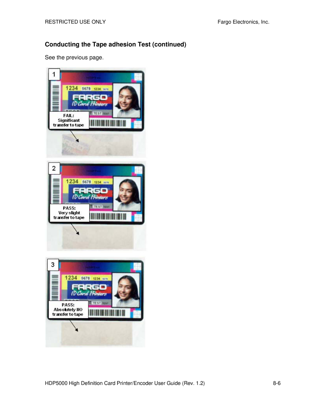
Conducting the Tape Adhesion Test
Conducting the Tape adhesion Test
See the previous
Conducting the Tape adhesion Test
Installing Printer Driver Updates
Printer Driver Options
Setting up the Printer
Installing Printer Driver Updates
When prompted, do not have Windows print a test print
From Disk window will appear
Setting Up the Printer Driver
Setting up Windows 2000/XP/2003
Using the OK, Cancel and Help buttons
Using the Card tab
Use this option to control specific Printer functions
Selecting the Card Size
Selecting the Card Type
Selecting the Card Type
Selecting the Card Type
Please see b on the previous
Setting the Orientation
Specifying the number of Copies
Selecting the Diagnostics button
This will launch the Diagnostic tool if installed
Selecting the Test Print button
Selecting the About button
Selecting the Toolbox button
Using the Device Options tab
This section describes the use of the Device Options tab
Detecting Supplies at Print Time Function
Detecting Supplies at Print Time Function
Detecting Supplies at Print Time Function
Adjusting the Ribbon Type
Use the Ribbon Type dropdown menu to match Ribbon type
Adjusting the Film Type
Using the Dual Sided Group Functions
Using the Dual Sided Print Both Sides option
Step Procedure
Select this option
Backside of the card
Using the Dual Sided Print Back Side Only option
Using the Options Group
Step Procedure
Using the Disable Printing option
Using the Image Color tab
Using the Image Color tab HDP5000
Display B Image Color tab Advanced Image Color window
Using the Quality Color Matching dropdown
Using the Quality Color Matching dropdown
Using the Quality Color Matching dropdown
Using the Quality Color Matching dropdown
Adjusting for the Resin Dither
Using the Advanced Image Color window
Using the Advanced Image Color window
See the previous
Using the Advanced Image Color window
Using the Advanced Image Color window
Using the Advanced Image Color window
Using the Default button on the Image Color tab
Using the Image Transfer tab
Adjusting the Image Position controls
Adjusting the Image Position controls
Adjusting the Transfer Dwell Time and Temperature
Adjusting the Transfer Dwell Time and Temperature
Adjusting the Transfer Dwell Time and Temperature
Adjusting the Transfer Dwell Time and Temperature
Using the Default button
Using the Magnetic Encoding tab
Magnetic Encoding
Using the Encoding Mode dropdown list
Category Description
ISO Encoding
Using the Encoding Mode dropdown list
Category Description Custom Encoding
Category Description Raw Binary
Encoding selection
String rather than a formatted set of characters. Note
Category Description JIS II Encoding
Selecting the Coercivity/Magnetic Track
Reviewing the Shift Data Left Function
Reviewing the Magnetic Track Options
Reviewing the Magnetic Track Options
Using the Magnetic Track Options
Using the Magnetic Track Options
Using the Character Size buttons
Using the Ascii Offset dropdown list
Using the Bit Density dropdown list
Using the LRC Generation dropdown list
Using the Encoding Mode dropdown list
Reviewing the ISO Track Locations
Sending the Track Information
Ascii See the table below
Reviewing the Sample String
Track Start End Field Valid Characters Maximum
Ascii 106 See the table below
Reviewing the Ascii Code and Character Table
Using the Default button Image Transfer tab
Using the Lamination tab HDP5000-LC
Selecting the Lamination Position
Adjusting the Lamination Speed Transfer Dwell Time
Selecting the Lamination Side dropdown menu
No Flipper Single Side Card Lamination Unit Lower
Dual Side Card Lamination Unit
Selecting the Lamination Type
Selecting the Lamination Type
See previous
Upper Limit = 170.0 Celsius
Adjusting the Lamination Temperature
Default = 145.4 Celsius
Lower Limit = 50.0 Celsius
Selecting the Defaults button
Using the K Panel Resin tab
Using the Scroll controls
Controls Description
Using the Click and Drag capability
Using the Add and Delete buttons
Selecting inches or mm radio button
Selecting the Full Card
Selecting the Defined Areas
Selecting the Undefined Areas
Defining the Area to activate the Card Grid
Measuring the Total Card area
Measuring the Area to be positioned on the Card
Selecting the Print YMC under the K and Print K Only options
Selecting the Print YMC under the K and Print K Only options
Using the Printer Supplies tab
Reviewing Information on the Supplies tab
Lamination Cartridge 1 Level Type, Reorder Number and Gauge
Lamination Cartridge 2 Level Type, Reorder Number and Gauge
Relates to the procedure on the previous
Reviewing Information on the Supplies tab
Accessing the Toolbox
This section describes the Toolbox function
Selecting the Configuration tab
Using the Configuration Tab
Using the Optional Printer Features Group Box
Using the Event Monitoring Group Box
Reviewing the Ribbon Low message
Display Ribbon Low dialog
Reviewing the Laminate Low Message
Using the Film Low message
Selecting the Set Language for Printer LCD Display Group Box
Selecting the Calibrate Laminator tab
Calibrate Passed
Selecting the Calibrate Film tab
Selecting the Calibrate Ribbon tab
Selecting the Clean Printer tab
Selecting the Clean Printer tab
See the procedure on the previous
Using the Clean Printer Group Box
Selecting the Advanced Settings tab
Selecting the Advanced Settings tab
Restore Defaults Button Restores default values
Reviewing the No Printer Connected error message
Reviewing the Value outside the Range error message
Cleaning
Using the Required Supplies
Safety Messages review carefully
Accessing the Clean Printer tab
Cleaning the Printer Platen Roller and Card Feed Rollers
Cleaning the Printer Platen Roller and Card Feed Rollers
Cleaning Procedures
Cleaning inside the Printer
Cleaning outside the Printer
Cleaning the Printhead
Replacing the Card Cleaning Roller
Steps Procedure
Cleaning the Magnetic Encoder
Reviewing the Card tab and Diagnostic button
Display a Card tab Diagnostics button
Reviewing the Card tab and Diagnostic button
Clean the Printhead with a Printhead swab
Cloth
Be sure to enclose any necessary paperwork, test cards, etc
Firmware Updates
Performing the Firmware Updates
Performing the Firmware Updates
Click on the Firmware selection box
Using the drop down menu, select the Printer
This will launch the Fargo Support
Click on the Go button, as shown below
Dialog
Click on the Save button to save the file
Completed
Designated files
Step
This completes the Firmware Update process
Contacting Fargo Technical Support
Finding out when a Fargo Card Printer was manufactured
Reading the Serial Numbers on a Fargo Printer
Reviewing Example No Serial Number A1280224
Reviewing Spare Parts Lists
Reviewing Spare Parts List for HDP5000 and HDP5000-LC
Glossary of Terms
Term Definition
Glossary of Terms
Glossary of Terms
Glossary of Terms
Glossary of Terms
Eeprom
Eprom
Glossary of Terms
Glossary of Terms
ISO
Glossary of Terms
Glossary of Terms
Glossary of Terms
PET
PVC
Resin Semi-solid material
RGB
Glossary of Terms
TAC
PVC
Cyan C
Designation of colored Ribbon by the panels of color
Order in which they are printed Yellow Y, Magenta M
Order in which they are printed Yellow Y, Magenta M, Cyan
Index
Embedded contaminants
No MiFare Encoder No Prox Encoder
Scroll controls K Panel
WordPad