Edition AB
Simovert
Page
Contents
10-1
11-1
12-1
13-1
14-1
15-1
17-2
16-1
17-1
17.1
Definitions and Warnings
Definitions and Warnings 01.2004
Standing Standing / Sitting
Sitting
General
Installation
Maintenance and servicing
Keep these safety instructions in a safe place
Description
DC link voltage
Operating range
Description 01.2004
Configuration Operation and control options
Initial Start-Up
Invertors after completing the basic
Energizing the power and the unit
Persons and equipment can occur by
You are advised to only connect
Transport Storage Unpacking Scope of delivery type G
Transport, Storage, Unpacking
Scope of delivery type J
Box options
Clearances
Installation
Installing the units
Point of installation
AFE basic mains module with CleanPower filter
Mounting dimensions and dimension sheets
Current Voltage
Mounting dimensions of AFE reactor
Partitions
AFE inverter construction type G
Door/roof openings
An arcing short-circuit must be prevented by the provision
Opening cross sections
Technical filter data in accordance with DIN
Filters
Following filter mat is approved for use
Fibroidelastov made by DELBAG-Luftfilter Gmbh
Water cooling
Built-in components
Roof section
AFE inverter construction type J
Appendix
Masterdrives VC inverters
01.2004 Installation
Filters
Mlfb
Fan, flow rate, opening cross- sections
Implementation
DC auxiliary
Supply
Slot 2 can be used for technology boards T100, T300, TSY
Installing the optional boards
Opened until at least after this delay time
Boards may only be replaced by qualified personnel
Installation 01.2004
Installation in Conformance with EMC Regulations
Connecting-Up and Wiring
AFE reactor connection
AFE basic mains module and CleanPower filter
X3 connector terminal
Connection overviews
U2/T1 V2/T2 W2/T3
Fan
+ D/L
Electronics box for boards Cusa X9 connector
DC connection
Fan connection 230 V 1 AC
210 a 3NE1 227-0 250 a 3NA3 144 250 a
Mains
Example configuration -7 for construction type J shows a
Control transformer must be protected by a 6 a fuse
Directly from the plant
Typical circuit for AFE chassis unit, construction type J
AFE inverter and AFE reactor
Power connections
Fan supply
Auxiliary power supply, precharging
Protective conductor connection
X9 external DC 24 V supply, precharging contactor control
Control terminal
Connectors for
Control terminals
Standard connections of the AFE inverter
View of Cusa
Terminal strip
Connecting up control cables
Terminal assignments
X100 control
Terminal Name Function Range
X101 control
Possible cross- .5 mm 2 AWG
X102 control
Pin Name Function Range
X300 serial interface
Digital outputs
Factory setting
Digital inputs/outputs
Connection
Dual-port Ram DPR for SCB, TSY, CB, TB
Only one of the above possible connections may be used
View of option board VSB
Voltage Sensing Board VSB
VSB
Connector assignments
Basic Function Check
Commissioning of the equipment
Please check
P052 =
Reset is run P052 automatically returns to
Checking actual value acquisition and precharging
P561 =
Explanation of Terminology and Functionality of the AFE
Data sets
10-1
Function Diagrams
Switchover, basic/reserve setting Basic/Resv
Switchover of reserve data set RDS
10-2
Parameterization
Examples
11-1
Key Meaning Function
Setting parameters via the PMU
Key
Toggle key
Example
Input rated supply voltage Input line frequency in Hz
Menu selection Closed-loop control settings
Start-up parameterization
Select language
Function selection P052
Factory setting P052 = 1 Parameter reset
To change P070
Access level Expert Mode
Initialization Mlfb input P052 =
Function Condition Result
Download P052 =
Select Return
Select Download
P051 = P090 = P091 =
Hardware configuration P052 =
TB installed in the electronics box of the converter
007, Starting Lockout 008 or Ready for on 009 states
Select Closed-loop control settings
Closed-loop control settings P052 =
Parameter List
Key to parameter list
12-1
R006 DC Bus Volts
General visualization parameters
R001 Operating status
R004 Output Amps
R032 Line frequency
12-3
R013 Operat. hours
R030 Line volts
P051 Access Level
General parameters
P052 Function Select
P054 OP Backlight
12-5
Drive data
R089 Board Position
12-7
R082 Line filter L/%
P083 Precharging
P091 Board Position
Hardware configuration
Closed-loop control
R152 Active RDS
12-10
R139
R150 Control status
P161 Startgen,max
P164 Operating mode
12-11
P160 Startmot,max
12-12
P308 Sampling Time
P325 MC switch-on del
P329 MCInvEnableDel
12-13
P409 Line contac. del
Functions
P387
P408 Forming time
Setpoint channel
P518 Deviation Time
12-16
Control and status bit connections
12-18
P576 Src. ext V ok
P575 Src No Ext Fault1
12-19
P572
P588 Src No Ext Warn1
P586 Src No ExtFault2
12-20
P587 Src.slave AFE
12-21
12-22
12-23
12-24
P629 DstPrechrgContEn
P631 Dst Pre-Charging
P657 Cusa AnalogOutOffs
P660 SCI AnalogInConf
Analog inputs/outputs
P656 Cusa AnalogOutGain
P665 SCI AnaOut Gain
P662 SCI AnalogInOffs
12-26
P664 SCI AnaOutActVal
P684 SCom/SCB Baud
Interface configuration
P682 SCB Protocol
P683 SCom/SCB BusAddr
P689 SCB Peer2PeerExt
12-28
P686 SCom/SCB # PrDat
P687 SCom/SCB TlgOFF
12-29
P694 CB/TB Act Values
P695 CB/TB TlgOFFTime
12-30
R723 PCB Code
Diagnostic functions
R721 SW Generat.Date
R722
R730 SCB Diagnosis
12-32
R748 Trip Time
12-33
P799 Special Access
Gating unit
Factory parameters
P927 Parameter Access
Profile parameters
P928 Src Base/Reserve
R949 Fault Value
R951 Fault Texts
12-36
12-37
12-38
12-39
12-40
Application
Control and Status Words
Control word
Introduction
Display of control word on PMU seven-segment display
Multiple connections are permitted
Control word
Bit No. meaning
Factory setting applies only when P077 =
Control word 1 visualization parameter r550 or r967
Designation
Parameter No
Control word 2 visualization parameter r551
Table X external terminals
Sources for control words 1
Table D
Table a
Table B
Table C
Table H
Table E
Table F
Table G
13-8
0000 0001 2004 3004 4501 4502 4503 4504 4505
Bit 0 on / OFF1 command ↑ on / L OFF1 Condition
Bit 1 OFF2 command L OFF2 electrical Condition
Description of the control word bits
Bit 10 Control via PLC command H Control via PLC Condition
Bit 7 Acknowledge command ↑ Acknowledge Condition
Bit 8 Inching 1 on command ↑ Inching 1 on / L Inching 1 OFF
Bit 9 Inching 2 on command ↑ Inching 2 on / L Inching 2 OFF
Bit 19 Reserved Bit 20 Reserved
Bit 28 External alarm 1 command L External alarm Condition
Bit 29 External alarm 2 command L External alarm Condition
Master AFE
13-13
High signal
Setpoint channel and closed-loop control are activated
Bit 31 Reserved
PMU display Status word
Status word
Status word 1 visualization parameter r552 or r968
Destination
Destination
13-15
Bit #
= High Select = Low Destin Bit Ready for on P600.x
Status word 2 visualization parameter r553
= 1 0000 1001 1002 1003
13-17
= High Select = Low Destin
= 3
Description of the status word bits
Bit 0 Ready for on signal H High signal
Bit 1 Ready to Run signal H High signal
Bit 2 Run signal H High signal
Bit 6 Starting lockout signal H High signal
Bit 7 Alarm signal H High signal
Bit 8 Setpoint/actual value deviation signal L LOW signal
Bit 22 AFE i2t alarm signal H High signal Meaning
Bit 19 External fault 1 signal H High signal
Bit 20 External fault 2 signal H High signal
Bit 21 External alarm signal H High signal
Bit 23 AFE overtemperature fault signal H High signal
F003 Line overvoltage
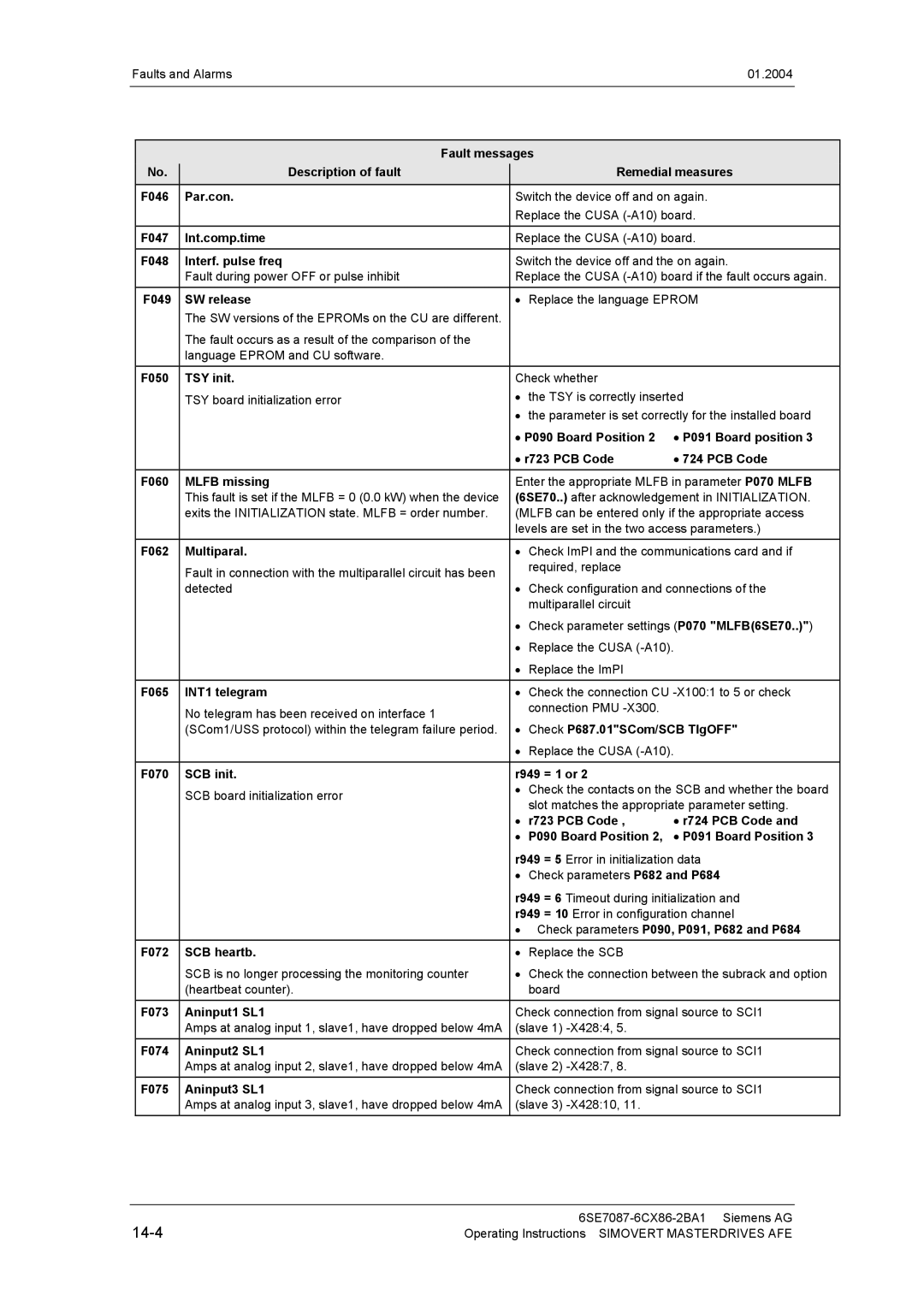
Faults and Alarms
Faults
Compare with P071 Line voltage
14-2
14-3
14-4
14-5
Alarms
14-7
Fatal errors FF
Personnel
Maintenance
Simovert Masterdrives units are operated at high voltages
National electrical codes VBG 4 in Germany
Position Equipment designation Brief description
CleanPower filter
Electrical components
AFE basic mains module
Replacing the fan
AFE inverter maintenance
Replacement
Fan assembly weighs about 30 kg
Replacing the starting capacitor
Replacing the fan fuses construction type J only
Capacitor battery weighs up to 30 kg
Replacing the capacitor battery
PMU with adapter section on the electronics box
Replacing the PMU
Fuses
Fan fuses for AFE inverters
15.3.2 DC fuses
Number is made up
Forming
How the serial
Example A-J60147512345
Switch on AFE
P408 P052 = Key
End
Technical Data
CleanPower filter AFE basic mains module
17-1
17-2
AFE basic mains module and CleanPower filter
17-3
6SE703x-xES87-1FG1
AFE reactor for construction type G
AFE reactor for construction type J
17-4
17-5
AFE inverter
Derating curves
Designation Value
17-7
Environmental Friendliness
Order No 6SE70
Certificates Confirmation
Equipment
Type
AC drive converter
Equipment Type Order No
19-3
Type 6SE70 Chassis units AC-AC and DC-AC
Operating manual
Contents
Appendix
Appendix to
Page
Page
Page
SIMOVERT-MASTERDRIVES AFE Siemens AG
FKBL1-VSB1
Edition Internal Item Number A5E00243916
Chapter Changes Pages Version date
Siemens AG