DVW-707/707P DVW-709WS/709WSP DVW-790WS/790WSP
Warnung
Recycling NICKEL-CADMIUM Batteries
Page
Table of Contents
Mechanical Deck Parts Replacement
Audio IN, Audio OUT CH1, CH2, DC IN, DC OUT
Tape Path Adjustment
VTR System Alignment
DVW-790WS/709WS/707
Camera System Electrical Alignment Only for DVW-707/707P
Page
Contents
Purpose of this manual
Related manuals
Fixtures and Adjustment Equipment
Fixtures
Illust No. Part No Description Usage
Illust No Description Usage
Adjustment Equipment
Equipment Model Name
Using the Extension Boards
Using the EX-655 and EX-656 Boards
Procedure
Board to be Extension board Reference Checked
Using the EX-657 and EX-658 Boards
When extending the DCP board assembly
Using the EX-667 Board
SV-210 Board
DC-DC Converter
DIF-75 Board Optional Board BKDW-702
CN2
CN2CN22
Disconnecting/Reconnecting Flexible Card Wires
Disconnecting
Reconnecting
IC Link
Description on EEPROM/NV-RAM Data
Spare CCD Units
Description on CCD Block Number
Setting/Adjustment After Board Replacement
Adjusting After Eeprom Replacement
Eeprom on the ES-23 Board
Ref. No. Address Data stored
DC Fans Precaution
Setting/Adjusting After Board Replacements
Board Setting/Adjusting after Replacement
Page
Service Mode
About the Setup Card
How to Enter the Service Mode
Data Structure
Fundamental Operation of the Setup Menu
Contents of Setup Menu
White Preset
Master Gain LOW
MID
High
Setup Card Read →CAM
Write →CARD
ID Edit
Write Protect
VTR Mode
Function 2/2 DCC Function FIX/DCC/ADP.K
SEL DCC
FIX
VF Setting Zebra 1 Detect
Zebra 1 Aperture
Zebra 2 Detect
Zebra Select
Burst Phase
RGB Setup LVL
ENC Setup LVL
Level Skin Tone DTL
Level Black
Flare
Test OUT ENC/R/G/B
Level Gamma Table
Level Phase
SC Phase
Iris Mode
Iris Weight
Adjustment
Shading G
SAW
Para
Preset WHT
Offset WHT
Offset Whitea
WARM-COOLA
Battery
Operation B-G SEL
LOW Light
LOW Light Level
Delay
Data Reset
Service
Operation AWB Level Gate
Menu SEL Setup Card
VF Setting
Menu SEL Marker 1/3
Marker 2/3
Resolution
Measurement
Modulation
Sensitivity
AD Gain AD Clock Phase
Clock Phase
ND Comp ND Detection OFF/EXEC/RESET
VTR ADJ EQ Adjustment
Display Description
DP DIAG.STATUS
MPX
DTL
ROM
Setup Menu List
Setup C RM-P9 RM-B150 SET C-SET Remark
Turbo YES
Setup C
VTR Mode YES OFF REC Inhibit CCU Assignable SW
Remark
Shutter EVS YES CLS
SET Remark
YES Level
ENC Y Level YES Black Flare Test OUT
SC 0/180 SEL
RM-B150 SET C-SET Remark
Preset WHT Color Temp P YES
Delay YES
REC Tally YES Upper Time Code Disp OFF Loop Recording
FRM Shutter FRM Shutter Unit YES OFF
YES Function 1/2 OFF Function 2/2 VF Setting Wide Screen
YES OFF Level 143DTL Level 243DTL Menu SEL
YES OFF Level 11SC-H
BC COMP.ADJ FIELD/FRAME YES Field Test OUT ENC Vsub
Gain TMP MOD.BAL. TMP SAW/REC Test Level Test SAW OFF
Preknee KS on Test OUT ENC Test SAW OFF
AD ADJ AD Gain AD Clock Phase ND Comp ND Detection OFF
YET
Setup C RM-P9 RM-B150 F-SET
MPX DTL ROM SV1 SV2 WSH
Page
Section Parts Replacement
Replacing Boards
Replacing the MB-810 and MB-811 Boards
MB-810 Board
MB-811 Board
Replacing the HN-260 Board
Replacing the CI-20 and CI-21 Boards
Removal
Replacing Boards
Reinstallation Required tools
Replacement
Adjustments after replacement
Replacing the CCD Unit and Its Components
Replacing the CCD Unit
Removal Removing the Front Assembly
CN1 CN2
Removing the ND Filter Knob
Removing the CC Filter Knob DVW-790WS/790WSP/709WS/709WSP
Removing the CCD Unit
DVW-790WS/790WSP/709WS/709WSP
Reinstallation Reinstalling the CCD Unit
Reinstalling the ND Filter Knob
DVW-790WS/709WS
DVW-707
Reinstalling the Front Assembly
Adjustment After Replacement Tape Running Adjustment
Electrical Alignment
Reinstallation
Adjustment After Replacement
CN3
Replacing the Boards Inside the CCD Unit
CN5 CN2
CN3 CN1 CN6
CN7 CN4
790WS/790WSP
Replacing the External Connectors/Switches
CH2, DC IN, DC OUT Connectors
Removing the Connector Box Assembly
Removing the CNB-11 Board
Removing the CNB Stay
Removing the RM-180 Board
Removing the Connector
Audio IN/AUDIO OUT connector
DC in connector
DC OUT connector
VF Connector
Power Switch, MIC in Connector
Power Switch
MIC in Connector
Shutter Switch
Replacing the Rotary Encoder
Replacing the DC Fans
Upper DC Fan
Lower DC Fan
Replacing the Camera SW Ornamental Plate
CP-329 board
Removal Required tool
Camera SW ornamental plate Mm or less Inside panel
Replacing the Card Door Assembly
Replacing the 40-pin Fitting Assembly
Reinstallation Required tool
General Information for Parts Replacement and Adjustment
About Cleaning Blade Tape Cleaner depending on model
About Tools
Threading End/Unthreading End Mode
Threading End Mode
Unthreading End Mode
Selection Procedure into the Unthreading End Mode
Manual Eject Assembly Removal/Installation
Installation
Index
Part Name Section
About screwdriver and torque reading
About stop washer
About oil and grease
Upper Drum Assembly Replacement
Overviews
Basic information
Preparations
Tools
Brush Assembly Removal
Removal Brush Cover Removal
Desoldering the Leads of Slip Ring Assembly
Upper Drum Assembly Removal
Installation Cleaning of Contact Surfaces
Upper Drum Assembly Installation
Upper Drum Eccentricity Adjustment Tool Installation
Upper Drum Eccentricity Adjustment
Upper Drum Eccentricity Adjustment Tool Removal
Soldering the Leads of Slip Ring Assembly
Brush Assembly Installation
Brush Cover Installation
Cleaning of Video Heads and Tape Running Surfaces
Adjustments After Replacement Tape Running Adjustment
Video Tracking Adjustment
CTL Head Height Adjustment
CTL Head Position Adjustment
Brush Assembly Replacement for Slip Ring
2x2 Brush assembly Brush cover Connector
Installation Brush Assembly Installation
Slip Ring Assembly Replacement
Remove this screw first
Slip Ring Assembly Removal
Installation Slip Ring Assembly Installation
Blue
Brush Assembly Installation
Drum Assembly Replacement
Removal Video Head Cleaner Removal
Disconnection of the Brush Assembly Connector
Drum Assembly Removal
CN2 CN3
Cleaning Drum assembly Positioning pins
Drum Assembly Installation
Connection of the Brush Assembly Connector
Video Head Cleaner Installation
Cleaning of Video Heads and Tape Running Surface
CUE Head Height Adjustment
Video System Adjustment
Pinch Roller Replacement
Installation Install Shaft Cleaning
Pinch Roller Installation
Pinch Roller Cleaning
Removal Pinch Roller Removal
HC Roller Assembly Replacement for Video Heads
Removal Mode Selection
VH Cleaner Assembly Removal
Installation HC Roller Replacement
VH Cleaner Assembly Installation
Operation Ceck
CUE Brush Replacement for CUE Head
Manual Eject Assembly Removal
Installation CUE Brush Replacement
Manual Eject Assembly Installation
Operation Check
Brake Band Assembly Replacement
Brake Band Assembly Removal
Removal Band Holder Removal
Installation Reel Table Cleaning
Brake Band Assembly Installation
Band Holder Installation
FWD Back Tension Adjustment
Soft Brake Assembly Replacement
Adjustment after replacement
Removal Soft Brake Assembly Removal
Soft Brake Assembly Installation
Adjustment After Replacement Brake Torque Check
10. S/T Idler Assembly Replacement
Or T Idler Assembly Removal
Installation Cleaning of the Installation Shaft
Or T Idler Assembly Installation
4x2.5
Swing Gear Assembly Replacement
Removal Removal of the Swing Gear Assembly Fixing Screw
Mechanical Deck Assembly Removal
Swing Gear Assembly Removal
Installation Swing Gear Assembly Installation
Mechanical Deck Assembly Installation
Swing Gear Assembly Fixation
Adjustment After Replacement Belt Tension Adjustment
Timing Belt Replacement
Removal Mechanical Deck Assembly Removal
Installation Cleaning of the Pulleys
Timing Belt Installation
Timing Belt Removal
HN hole
Capstan Motor Replacement
Removal Manual Eject Assembly Removal
Installation Capstan Motor Installation
Capstan Motor Removal
With drop-safe Pin of the chassis
Adjustments After Replacement Belt Tension Adjustment
CTL Head Replacement
Removal Entrance Head Assembly Removal
Installation CTL Head Replacement
Entrance Head Assembly Installation
Entrance Head Assembly Cleaning
Adjustments After Replacement Tape Running Adjustment
CUE Head Replacement
Gear Block Assembly Removal
Cassette Compartment Removal
CUE Head Block Assembly Removal
Installation CUE Head Replacement
CUE Head Block Installation
Cleaning of the Head
Cassette Compartment Installation
Gear Block AssembIy InstaIIation
Video Tracking Adjustmen
Audio System Adjustment
Reel Table Replacement
Removal Reel Table Removal S reel table removal
Reel table removal
Installation Reel Shaft Cleaning
Reel Table Installation
Reel Table Height Adjustment
Adjustments After Replacement FWD Back Tension Adjustment
Put the remaining poly washer s in the step
Pinch Arm Assembly Replacement
Removal Pinch Arm Assembly Removal
Installation Installing Shafts Cleaning
Applying Oil to Installing Shafts
Pinch Arm Assembly Installation
Pinch Eoller Cleaning
Sensor a Detection Pin Replacement
Removal Sensor Cover a Removal
Installation Detection Pins Installation
Sensor Cover a Installation
Sensor B Detection Pin Replacement
Removal Sensor Cover B Removal
Sensor Cover B Installation
Tension Regulator Arm Assembly Replacement
Tension Regulator Arm Assembly Removal
Removal Brake Band Removal
Installation Tension Regulator Arm Assembly Installation
Brake Band Installation
Tension Regulator S4 Guide Cleaning
Overviews
Preparations
Disconnection Brush Assembly Connector
Removal Cassette Guide Removal
Drawing Arm Removal
Driving Gear Removal
Catcher S Removal
Threading Link Assembly Removal
Slider
Threading base
Threading gear assembly installation
Parts Replacement
Threading Link Assembly Installation
Catcher S Installation
Driving Gear Installation
Drawing Arm Installation
100
Connection the Brush Assembly Connector
Cassette Guide Installation
Cleaning of the Head and the Tape Running Surface
Replacement of Loading Motor
Motor Removal
Pinion Gear Removal
Installation Pinion Gear Installation
Motor Installation
Gear Block Assembly Installation
Replacement of FE Head
108
FE Head Removal
Remove the one screw and remove the FE head
Harness Removal
Harness Soldering
BLK GRY
Installation FE Head Installation
Replacement of Tape Cleaner
Tape Cleaner Removal
Installation Tape Cleaner Installation
Replacement of Tape Guide
Tape Guide Removal
Installation Tape Guide Installation
114
Adjustment After Replacement Tape Guide Height Adjustment
115
116
Mechanical Deck Replacement
Removing the Mechanical Deck
Attaching the Mechanical Deck
Mechanical Adjustment
Tension Regulator Operating Position Adjustment
Check Mode Selection
Adjustment Position Adjustment
Point for adjustment
Mode Cancel
Tension Regulator Operating Position Check
FWD Back Tension Adjustment
Tool
Check REC Mode Setting
Adjustment Eject Mode Setting
Back Tension Adjustment
Reference of adjustment
Brake Torque Check
Check Setting
Case that the value does not meet the specification
Adjustment Mode Cancel
Side Brake Torque Check
Belt Tension Adjustment
Adjustment Belt Tension Adjustment
Page
Index Location of Tape Path System
Contents
Tape Running Adjustment
Checks Play Mode Playing back the tape top
Specifications
Drum Entrance Side Threading End Mode
FWD Mode Fast forward at tape top
REW Mode Rewind at tape top
Play Mode Playback at tape end
REV Mode Rewind at tape end
FWD Mode Fast forward at tape end
REW Mode Rewind at tape end
Checks After Adjustment Video Tracking Check
Tape Running Re-check at the Drum Entrance Side
Tape Running Check at the Drum Exit Side
CTL Head Height Check
Drum Exit Side Checks Play Mode Playing back the tape top
REV Mode Rewind at tape end
Tape Running Check Around the Capstan Shaft
Adjustments T2 and T3 Guides Height Adjustment
Reference for adjustment
CUE Head Azimuth Adjustment
Tape Running Re-check at the Drum Exit Side
Video Tracking Adjustment
Checks Play Mode
Play Mode
RF Waveform Check
REV search mode
Drum exit side Tracking Adjustment Drum Exit Side
Video Tracking Re-check
Tape Running Check
CUE Head Height Check
CTL Head Height Adjustment
If the Level Increases When Pushing Up the Tape
Adjustments After Adjustment CTL Head Position Adjustment
Checks Play Back
CTL Head Position Adjustment
Adjustments CTL Head Position Adjustment
Adjustment After Adjustment CUE/TC Head Position Adjustment
CTL Head Position Re-check
CUE Head Height Adjustment
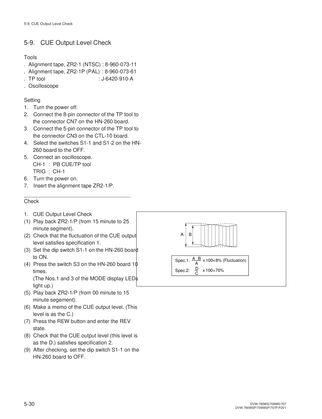
Play back ZR2-1/P from 00 minute to 15 minute segment
Adjustments CUE Head Height Adjustments
CUE Head Head-to-contact Check
CUE Head Azimuth Check
CUE Head Head-to-tape Contact Adjustment
CUE Head Azimuth Check
CUE Head Head-to-tape Contact Adjustment
Adjustments CUE Head Head-to-tape Contact Adjustment
CUE Head Head-to-tape Contact Check
CUE Head Head-to-tape Contact Re- check
CUE/TC Head Position Adjustment
Adjustments Play Back
Adjustment
CUE/TC Head Position Re-check
SV REF CF
Re-check according to the steps 1
CUE Output Level Check
Check CUE Output Level Check
Preparation
Power System Adjustment
Battery End Detection Voltage Adjustment
Adjustment Procedure
Check Procedure
Servo System Adjustment
Automatic Servo Adjustment
Setting upon Completion of Adjustment
Automatic PG Phase Adjustment
Manual PG Phase Adjustment
Audio System Adjustment
1. D/A Level Adjustment
GND
Output Limiter Adjustment
AGC Level Adjustment
CUE Playback Level Adjustment
CUE Recording Bias Adjustment
CUE Recording Level Adjustment
Video System Adjustment
Preparation
Playback Equalizer Automatic Adjustment
Confirmation Procedure
Recording Current Automatic Adjustment
Precaution
Page
General Information for Electrical Adjustment
Initial Switch Settings
Screen Mode Setting
Equipment/Fixtures
Initial Setting
Maintaining the Grayscale Chart
Handling precautions
Replacement period when the chart is used as the reference
Murakami Color Research Laboratory
Setting Illumination when the reflective chart is used
VCO Cont Frequency Check
Test OUT → ENC
INT SC Frequency
Video GEN OUT Lock
AD Clock Phase Adjustment
AD Clock Phase
Clock Phase
IRE Ntsc
ENC OUT Adjustment
ENC Level Adjustment
Chroma Adjustment
INT SC Phase Adjustment
SC Phase
Setting After Adjustment
Blanking Width
Test OUT Level Adjustment
RGB Setup
RGB Sync
RGB Level
Modulator Balance Adjustment
→ CAM/ON
Test SAW Adjustment
R/B AD Gain Adjustment
Knee → OFF
AD Gain
Test SAW → OFF Gamma
VA Gain Adjustment
S35*PRESET WHT Color Temp P
Gamma → on
Preset White Adjustment
Shading Adjustment
Black Shading Adjustment
White Shading Adjustment
S30 *W-SHADING G
S32 *W-SHADING B
Gamma Correction Adjustment
Master Gamma
Test SAW → OFF
Black Set Adjustment
Setting After Aadjustment
Flare Adjustment
Flare
Knee and White Clip Adjustments
Manual Knee and White Clip Adjustments
DCC Pre Knee Adjustment
Gamma → OFF Test SAW
Preknee DCC
DCC Knee Adjustment
DCC Point →
DCC D Range
Detail Signal Adjustment
Crispening Adjustment
Level Depandent Adjustment
Detail Frequency Adjustment
16-4. H/V Ratio Adjustment
Ratio
Detail Level Adjustment
Knee Aperture Adjustment
Knee APT
APT.LVL
Detail Black Clip Adjustment
169/43 Mode → Select the 43 mode
17-4. H/V Ratio Adjustment
Detail LVL
DTL H B . Clip 43 Factory setting
Skin Tone Adjustment
Zebra Adjustment
Automatic Iris Adjustment
Iris Mode
Iris Weight → 0 MIN
Iris Weight
Adjustment After Replacing Filter Disk Unit
ND Detection → Exec
Initial Setting for Switches
Lens
Iris → C Close
S06*MASTER Gain
Maintaining the Grayscale Chart
Setting Illumination when the reflective chart is used
Video OUT
GEN SC Lock OUT
Spec = 40 ± 1 IRE Ntsc = 300 ± 7 mV PAL
On the setup menu, adjust as follows S40*ENC ADJ
Spec 10.9 ± 0.2 us Ntsc 12.0 ± 0.3 us PAL
Spec = 100 ± 2 IRE Ntsc = 700 ± 14 mV PAL
Spec = 100 ± 2 IRE Ntsc = 700 ± 10 mV PAL
Make sure that the carrier leakage at portion B is not
S35*PRESET WHT
Fine Whitep
S48*B-SHADING G
S50*B-SHADING B
Para
On the setup menu, adjust as follows S25 *LEVEL
Spec ± 1 IRE Ntsc ± 7 mV PAL
Spec 109 ± 2 IRE Ntsc 763 ± 14 mV PAL
Spec ± 2 IRE Ntsc
DCC Knee Adjustment
Reduce the noise at gray portion to a
16-4. H/V Ratio Adjustment
Detail Level Adjustment
On the setup menu, set as follows S12*FUNCTION 1/2
Component in the saturation detection
ZEBRA1 APT. LVL → 1 %
Adjustment Procefure
Adjustment After Replacing Filter Disk Unit
DVW-790WS/709WS/707 DVW-790WSP/709WSP/707P P2V1
Sony Corporation