IR2200/iR2800 IR3300
Copyright 2001 Canon INC
Symbols Used
Symbol Description
Reader Unit
Outline of the Manual
System Unit
Printer Unit
Troubleshooting
Introduction
System Unit
Contents
Installation
Chapter General Description
Type
Specifications
Main Body
Systems
Ltrr
Functions
T01-101-03
Single-sided copying mode
T01-101-04
DADF-H1
T01-101-05
6GB
Others
T01-101-06
B5R
T01-101-07
A4R
A5R
T01-101-08
Side Paper Deck-L1
T01-102-01
ADF
Names of Parts
External View
F01-201-01
F01-201-02 10 S
Cross Section
F01-202-01
T01-202-01 12 S
F01-301-01
System Configuration
Functional Construction
F01-302-01 14 S
Outline of the Electrical Circuitry
Construction of the Electrical Circuit
F01-303-01
Wiring Diagram of the Major PCBs
Inputs to and Outputs from the Major PCBs
DADF-H1
Configuration with Accessories
Accessories for Original/Paper Feeding
F01-304-01 16 S
Accessory Boards
F01-304-02
Chapter Main Controller
Basic Construction
F02-101-01
HDD
Outline
Main Controller PCB
T02-102-01
F02-102-01
Start-Up Sequence
F02-103-01
Start-Up Sequence
F02-103-02
F02-103-03
F02-201-01
Digital Image Processing
Outline
Input Image Processing
Binary dither screen method
Binary Processing error diffusion method T-BIC
Image Memory Control
Sdram
Output Image Processing
When Generating Read Images
When Generating Printer PDL Images
Smoothing
PS19S
Soft Counters
T02-301-01
PS21S
F02-301-01
F02-301-02 12 S
OFF
T02-301-02
T02-301-03
OPTIONUSERCOUNTER3
OPTIONUSERCOUNTER1
OPTIONUSERCOUNTER2
OPTIONUSERCOUNTER4
Standby Mode normal operation
Controlling the Power Supply
Power Supply Modes
Sleep Mode
Shift from Standby Mode to Sleep Mode
Shift from Sleep Mode 1 to Standby Mode
Shift from Sleep Mode 2 to Sleep Mode
Turning Off the Power
Shift from Sleep Mode 2 to Standby Mode
Network PCB
New Functions
Hard Disk Spool
F02-501-01 18 S
SMB Printing
F02-502-01
LPD Banner
F02-503-01 20 S
Chapter Installation
Selecting the Site of Installation
F03-100-01
F03-100-02
Unpacking and Installation
Before Starting the Work
Unpacking and Removing the Fixing Materials
Installation
Mounting the Scanner
Removing the Dummy Drum
Supplying the Toner
Installation
Installation
Mounting the Drum Unit
11 S
Stirring the Toner
Setting the Cassette
Set the dial as indicated
LTR
Checking the Images/Operations
17 S
Checking the Network Connection
Connecting to the Network
Using the Ping Function
Copiertestpingnetwork
Checking the Connection of the Network Cable
Troubleshooting the Network
Making a Check Using a Remote Host Address
Making a Check Using a Loop-Back Address
Making a Check Using a Local Host Address
Relocating the Machine
Preparing for Relocation
Lifting the Machine Off the Pedestal
22 S
Installing the Card Reader-C1
Copierfunctioninstallcard
24 S
25 S
Installing the Document Tray-D2
26 S
Replacing the Drum Unit
28 S
29 S
Copierfunctiondpcd Gamma
30 S
Reader Unit
Basic Operation
Image Processing System
Chapter Basic Operation
CPU
Outline of Electrical Circuitry
Reader Controller PCB
RAM
Basic Sequence of Operations
Basic Sequence of Operations at Power-On
Basic Sequence of Operations in Book Mode
F01-202-02
Wiring of Major PCBs
Inputs to and Outputs from the Major PCBs
Chapter Original Exposure System
Outline of Operations
F02-101-01 F02-101-02
LAMP1
F02-102-02
Sequence of Operations original exposure
Book Mode, 1 Original, Copyboard Closed
F02-102-04
Book Mode, 1 Original, Copyboard Cover Open
F02-102-03
Changing the Reproduction Ratio in Sub Scanning Direction
Enlargement/Reduction zoom
Changing the Reproduction Ratio in Main Scanning Direction
Scanner Drive System
F02-202-01
Controlling the Motor When Scanning an Image
Controlling the Scanner Motor
F02-202-02
COPIERFUNCTIONCCDSHDG-POS shading position adjust- ment
E202 HP detection error
E204 image leading edge detection error
F02-202-03
Turning On/Off the Lamp
Controlling the Scanning Lamp LA2
Scanning Lamp
F02-302-01
E225
Detecting an Error
E220
10 R
Outline of Detection
Detecting the Size of Originals
Points of Detection
F02-402-01
12 R
Outline of Detection Operation
F02-404-01
Book Mode, 1 Original, Copyboard Cover Close
T02-404-01
F02-404-02
T02-404-02 14 R
Disassembly and Assembly
F02-501-01 F02-501-02 16 R
Exposure Lamp
Removing the Exposure Lamp
F02-501-03 F02-501-04
After Replacing the Scanning Lamp
Copierfunction CCDCCD-ADJ
F02-502-02 F02-502-03 18 R
Scanner Drive Assembly
Removing the Scanner Motor
Mounting the Motor Unit
F02-502-04 F02-502-05
Removing the Scanner Drive Cable
F02-502-06 20 R
Routing the Scanner Drive Cable
F02-502-07
Adjusting the Position of the No /No Mirror Base
Front Side F marking Rear Side R marking
F02-502-10 F02-502-11
Removing the HP Sensor
Sensors
Removing the Original Detection Unit
F02-503-01
F02-503-05
Removing the Original Cover Sensor
F02-503-04
26 R
PCBs
Removing the Inverter PCB
F02-504-01 F02-504-02 F02-504-03 F02-504-04
Chapter Image Processing System
Outline
CCD CCD PCB
Driving the CCD
F03-202-01 CCD Block Diagram
Analog Image Processing
F03-201-01
F03-205-01
Gain Correction and Offset Correction of the CCD Output
A/D Conversion of the CCD Output
Shading Correction
F03-301-01
F03-302-01
Shading Adjustment
Shading Correction
Edge Gain Correction ADF in use
F03-302-02
F03-303-01
Auto Density Adjustment AE
ABC Circuit
F03-304-01
Related Service Mode
COPIERFUNCTIONCCDCCD-ADJ shading auto adjustment
Disassembly and Assembly
Removing the Reader Right Cover
External Covers
External Covers
F03-401-01
Copierfunctionccd SH-PS-ST
Removing the Copyboard Glass
After Mounting the Copyboard Glass
F03-401-03
F03-402-01
CCDs
Removing the CCD Unit
F03-402-02 12 R
Points to Note When Replacing the CCD Unit
Copierfunction CCDEGGN-POS
Removing the Reader Upper Frame
Frames
Removing the Left ADF Base Unit
F03-403-01
Mounting the Reader Upper Frame
F03-403-03
When Replacing the Reader Controller PCB
Removing the Reader Controller PCB
Printer Unit
Introduction
Controlling the Transfer Charging Roller Bias
PICKUP/FEEDING System
Fixing System
Externals and Controls
PCB
Paper DECK-L1
Cassette Feeding UNIT-W1
Inner 2WAY TRAY-A1
Chapter Introduction
Cdrh Ordinances
Safety
Safety of Laser Light
F01-102-01 Cdrh Label
Handling the Laser System
F01-103-01 Laser Warning Label
Safety of Toner
Image Formation System
F01-201-01 Construction of the Machine
F01-201-02
Chapter Sequence of Operations
Basic Operations
T02-102-01 Control Functions
Outline for the Electrical Circuitry
DC Controller PCB
Dimm ROM
T02-103-01
Basic Sequence of Operations at Power-On
Basic Sequence of Operations
Increase in temperature for each specific period of time
T02-104-01
F02-104-01 Control Circuit Block Diagram
Controlling the Main Motor M2
F02-105-01
Chapter Laser Exposure System
Part 2Chapter 41.1 Outline of Laser Exposure System
T03-101-01
F03-101-01
T03-101-02
Sequence of Operations laser exposure system
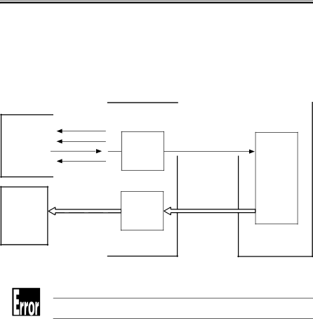
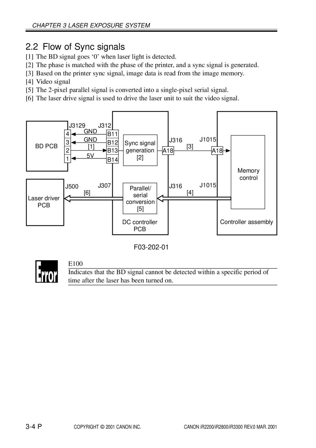
Generating Sync Signals
Part 2Chapter 42 Generating the BD Signal
F03-102-01
Flow of Sync signals
F03-202-01
Laser Driver Circuit
Controlling the Laser Unit
ADJUSTLASERPVE-OFST
ADJUSTLASERLA-OFF
Controlling the Laser Scanner Motor
Part 2 4.1 Outline
Disassembly and Assembly
F03-501-01
Laser Scanner Assembly
Removing the Laser Unit
F03-501-02
Chapter Image Formation System
Outline of Processes
T04-101-01
F04-101-01
Basic Sequence of Operations image formation system
F04-102-01
Controlling the Primary Charging Roller Bias
F04-201-01
Turning On/Off the Bias
Controlling the Current Voltage/Current to a Specific Level
F04-204-01
Temperature Correction of the DC Bias
Humidity Correction of the AC Bias
F04-205-01
Image Formation System
COPIERADJUSTHV-PRIAGS-OFST
COPIERADJUSTHV-PRIP-AC
COPIERADJUSTHV-PRIAGS-GAIN
COPIERADJUSTHV-PRIOFST1-AC
Controlling the Transfer Charging Roller Bias
F04-301-01
10 P
Controlling the Output by Operating Mode
Types of Modes
12 P
Turning On/Off the Cleaning Bias
F04-304-01
Controlling the Output
F04-401-01 14 P
Controlling the Separation Static Eliminator Bias
Part 2Chapter 58.3 Static Eliminator Separation Method
Controlling the Bias to a Specific Voltage Level
Part 2Chapter 57.2 Transfer Guide Type
Controlling the Transfer Guide Bias
Transfer Guide Bias
F04-501-01 16 P
F04-601-01
Primary Charging Roller Cleaning Mechanism
Part 2Chapter 510.1.5 Cleaning the Primary Charging Roller
Developing Assembly
F04-701-01 18 P
Controlling the Developing Bias
F04-702-01
Controlling the Level of the DC Developing Bias
Controlling the DC Developing Bias
Controlling the AC Developing Bias
20 P
Detecting the Level of Toner
F04-703-01
Drum Cleaner
F04-801-01 22 P
F04-801-02
Monitoring the Waste Toner Case
F04-802-01 24 P
Locking of the Waste Toner Feedscrew
26 P
F04-901-01
Pre-Exposure Lamp Unit
Removing the Pre-Exposure Lamp Unit
F04-902-01
Photosensitive Drum
Removing the Drum Unit
F04-902-02
Cleaning the Photosensitive Drum
F04-903-01
Transfer Charging Roller
Removing the Transfer Charging Roller
F04-903-02 30 P
F04-904-01 F04-904-02
Charging Roller Solenoid
Removing the Charging Roller Solenoid SL6
F04-904-03 F04-904-04 F04-904-05 32 P
F04-905-01
Developing Assembly
Removing the Developing Assembly
Removing the Toner Sensor
Removing the Grip Assembly
Removing the Developing Assembly Upper Cover
F04-905-02 F04-905-03
F04-905-05 F04-905-06
Removing the Blade Base Unit
Removing the Developing Cylinder
F04-905-07
F04-905-10 36 P
F04-905-08
F04-905-09
F04-905-13
F04-905-11
F04-905-12
F04-905-14
Positioning the Developing Assembly Magnetic Seal
Mounting the Developing Assembly Blade
F04-905-15
Removing the Paper Lint
When Removing the Paper Lint
Removing the Paper Lint
F04-906-01
F04-907-01 F04-907-02 F04-907-03 40 P
Waste Toner Case
Replacing the Waste Toner Case
Cleaning the Waste Toner Case
F04-907-04 F04-907-05 F04-907-06
Chapter PICK-UP/FEEDING System
Specifications and Construction
T05-101-01
Arrangement of Rollers
F05-101-01
Arrangement of Motors, Clutches, and Solenoids
F05-102-01
T05-102-01
Arrangement of Sensors
F05-103-01
Detecting Jams
Delay Jam
Cassette Pickup Assembly cassette 1
Sequence of Operations jam detection
T05-201-02
Other Delay Jams
F05-201-02
Jam History
F05-201-03 Power-On Stationary Jam
Stationary Jam
Common Stationary Jam
F05-301-01
Pickup Assembly
Pickup Control System
Outline
F05-303-01 10 P
Sequence of Operations pickup
Cassette
F05-304-01
Operation of the Cassette Lifter
Operation of the Lifter During Printing
Releasing the Lifter
Rotating the Pickup Roller
Switching the Pickup Roller Drive
Cassette Pickup Operation
Pickup Roller Shaft Reference
F05-305-02
F05-305-03 14 P
F05-306-02
Moving Up/Down the Pickup Roller
F05-306-01
F05-307-01 Retry Operation 16 P
Conditions for Detecting a Delay
Pickup Retry Operation
Paper Retraction
F05-307-02
Operation Other Than Cassette Pickup standby
F05-308-01 18 P
F05-308-02
F05-308-03 20 P
F05-308-04 Releasing the Lifter
T05-309-01 22 P
Detecting the Level of Paper
F05-309-01
Detecting the Presence/Absence of Paper Inside the Cassette
F05-310-01
Identifying the Size
AB-/Inch-Setting Switch
Identifying the Size of Paper
F05-402-01 24 P
F05-403-01 Rotary Label
Paper Size
A4R
Paper Size List
T05-403-01 List of Paper Sizes 26 P
Multifeeder
F05-501-01
Rear/Front Registration
Identifying the Size of Paper in the Multifeeder
Detecting the Width of Paper
Identifying the Length of Paper
Control System
COPIERADJUSTFEED-ADJREGIST
Controlling the Registration Roller
Through-Path Operation
COPIERADJUSTFEED-ADJADJ-REFE
Double-Sided Printing
Outline of Operations
F05-703-01
F05-703-02 32 P
Detecting the Horizontal Registration Position
T05-703-01
Operation
F05-703-02
T05-801-01
Controlling the Pickup Assembly Motor
Pickup Assembly Motor
F05-801-01
Disassembly and Assembly
F05-901-01
Pickup Assembly
Removing the Pickup Assembly
F05-901-02
F05-901-05 38 P
Removing the Pickup/Feeding/Separation Rollers
F05-901-04
F05-901-07 F05-901-08
Removing the Frame Lid
F05-901-06
F05-901-09 F05-901-10 F05-901-11 40 P
Removing the Pickup Motor
Remove the Vertical Path Cultch
F05-901-13
Removing the Horizontal Registration Sensor Shift Motor
F05-901-12
F05-901-14
F05-901-15
Adjusting the Cassette Rear Front Registration
Checking the Image Rear Front Position
COPIERFUNCTIONC1- ADJ-Y/C2-ADJ-Y/C3-ADJ-Y/ C4-ADJ-Y
F05-901-16
F05-901-17
F05-902-01
Multifeeder Tray Assembly
Removing the Multifeeder Tray Assembly
F05-902-02
F05-902-03
Removing the Pickup Cover
Removing the Multifeeder Tray Pickup Roller
F05-902-04
F05-902-06
Removing the Separation Pad
F05-902-05
F05-902-07 46 P
F05-902-08
Adjusting the Registration for the Multifeeder Rear Front
Attaching the Timing Belt of the Multifeeder Tray
F05-902-09
F05-902-10 48 P
F05-903-01
Feeding Assembly
Removing the Feeding Assembly
F05-903-02
Mounting the Feeding Assembly
F05-903-04 50 P
F05-904-01 F05-904-02 F05-904-03
Registration Roller Assembly
Removing the Registration Roller
F05-904-06 52 P
F05-904-04
F05-904-05
F05-904-07
Chapter Fixing System
Fixing system has the following major functions
T06-101-01
F06-101-01
F06-101-02
T06-101-02
F06-202-01
Fixing Drive System
Controlling the Fixing Roller Drive
F06-202-02
COPIERADJUSTFIXINGFX-FL-SP COPIERADJUSTFIXINGFX-FL-TH
Controlling the Fixing Film Speed
Controlling the Fixing Temperature
F06-301-01
Copieroptionbody
Temperature Control
T06-302-01
FIX-TEMP
Fixing Temperature Control
F06-302-01
Detecting Errors
F06-303-01
10 P
Disassembly and Assembly
Removing the Riser Guide
Fixing Assembly
Removing the Delivery Cover
F06-401-01
Removing the Fixing Film Unit
Removing the Fixing Assembly
Removing the Fixing Stepped Gear
F06-401-04 F06-401-05 F06-401-06
F06-401-07 F06-401-08
F06-401-09
F06-401-10 F06-401-11 F06-401-12
F06-401-13 F06-401-14 16 P
Removing the Cleaning Roller Unit
Removing the Lower Guide Ribs
F06-401-15
Removing the Fixing Drive Unit
Mounting the Locking Cam Unit
F06-401-16 F06-401-17
Chapter Externals and Controls
COPIERFUNCTIONPANELLED-CHK
Control Panel
F07-101-01
COPIERFUNCTIONPANELLED-OFF
T07-201-01
Arrangement, Functions, and Error Codes
Fans
F07-201-01
Sequence of Operations
Operation
1 2-Speed Control
F07-202-01
T07-301-01
Power Supply
Power Supply
Machine distributes power as follows
F07-301-01
F07-301-02
Power Outputs
T07-301-02
PCB
T07-302-01
Rated Outputs of the Main Power Supply PCB
Rated Output of the Composite Power Supply PCB
T07-303-01
Rated Outputs of the Accessories Power Supply PCB
T07-304-01
Protective Functions
Silent Mode
Others
Disassembly and Assembly
F07-501-01
F07-501-02 F07-501-03 14 P
Removing the Front Cover
Removing the Inside Cover
Removing the Support Cover
F07-501-04
F07-502-01
Control Panel
Removing the Control Panel
F07-502-02 16 P
Removing the Controller Cover
Points to Note When Replacing the DC Controller PCB
Removing the DC Controller PCB
F07-503-01
F07-503-04 18 P
Removing the HDD
F07-503-03
F07-503-05
Removing the HDD Unit
Removing the Controller Box Unit
F07-503-06
F07-503-08 20 P
Removing the Main Controller PCB
F07-503-07
12Removing the Accessories Power Supply
10When Replacing the Main Controller PCB
11Removing the Composite Power Supply
F07-503-09
13Removing the Main Power Supply
F07-503-11 22 P
Chapter Paper DECK-L1
Pickup
Pickup Operation
F08-101-01
Sequence of Pickup Operations deck
F08-101-02
Detecting the Presence/Absence of Paper
Switching the Deck Paper Size
Detecting Paper in the Deck
F08-102-01 F08-102-02
PS2D PS8D PS7D
Detecting the Level of Paper in the Deck
T08-102-01
Deck Lifter
F08-103-01
Indicating the Level of Paper deck front cover
F08-103-02
F08-104-01
Opening/Closing of the Compartment
Opening/Closing of the Compartment
Sequence of Operations opening/closing of the compartment
F08-104-02 10 P
Turning On/Off the Motor
Controlling the Deck Motor
Controlling the Deck Main Motor M1D
F08-105-01
Controlling the Deck Lifter Motor M2D
F08-105-02
M2D
PS1D
F08-201-01
T08-201-01 14 P
PS6D
F08-201-02
Intr Scan Print
Disassembly and Assembly
Sliding Out the Compartment
F08-301-01 F08-301-02
F08-301-03
F08-301-04 18 P
F08-301-06-A
Adjusting the Paper Level Indicator
F08-301-05
F08-301-06-B
Removing the Rear Cover
Moving the Deck Lifter
F08-301-07 20 P
F08-301-08 F08-301-10
Removing the Right Cover
Removing the Front Upper Cover
Removing the Upper Cover
F08-301-11 22 P
F08-302-02-A
Paper Deck Body
F08-302-01
F08-302-02-B
F08-302-03 24 P
Removing the Compartment
F08-302-04 F08-302-05
F08-302-06 F08-302-07 26 P
Copieroptionaccdk
Changing the Deck Paper Size
After Changing the Deck Paper Size
F08-302-08
F08-302-09
COPIERFUNCTIONDK- ADJ-Y
F08-302-10
Adjusting the Registration for the Deck
Adjusting the Position of the Support Member
F08-302-11
Removing the Deck Feeding Clutch CL1D
Drive System
Removing the Deck Pickup Clutch CL2D
F08-303-01-A
F08-303-02
Removing the Deck Main Motor M1D
Removing the Deck Lifter Motor M2D
F08-303-03
F08-303-05a F08-303-05b 32 P
Removing the Lifter Cable deck front
F08-303-04
F08-303-06
F08-303-07
Removing the Lifter Cable deck rear
F08-303-08 F08-303-09 34 P
F08-303-10 F08-303-11
Routing the Lifter Cable
F08-303-12 36 P
Removing the Deck Pickup Roller
Feeding Mechanism
Removing the Deck Pickup Unit
F08-304-01
F08-304-04 F08-304-05
Mounting the Deck Pickup Roller
Removing the Deck Pickup/Feeding Roller
F08-304-06 38 P
F08-304-07 F08-304-08
Orientation of the Deck Pickup/Feeding Roller
Removing the Deck Separation Roller
F08-304-09
Adjusting the Deck Separation Roller Pressure
F08-304-10 40 P
Position of the Deck Pickup Roller Releasing Solenoid SL1D
F08-304-11
Removing the Deck Drive PCB
Removing the Open Switch PCB
Electrical Mechanisms
F08-305-01
Chapter Cassette Feeding UNIT-W1
T09-101-01
Following rollers are used to move paper inside the machine
M2C
F09-103-01
M1C
CL1C
PS3C
F09-104-01
PS2C
Stationary Jams
Delay Jams
Sequence of Jam Detection
F09-301-01
Detecting the Presence/Absence of Paper Inside the Cas Sette
AB/Inch-Setting Switch
Disassembly and Assembly
F09-501-01
F09-501-02
F09-501-03 F09-501-04
F09-502-01 F09-502-02 12 P
Removing the Pickup Soleroid
Adjusting the Registration for the Cassette Rear Front
Removing the Pickup/Feeding/Separation Roller
Removing the Vertical Path Clutch
Removing the Cassette Size Detection Unit
F09-503-01 F09-503-02 14 P
Removing the Pedestal Controller PCB
F09-503-03
Removing the Pedestal Main Motor
Drive Mechanisms
Removing the Main Motor Drive Unit
F09-504-01 F09-504-02 16 P
Mounting the Pedestal Main Motor
F09-504-03
Chapter Inner 2 WAY TRAY-A1
F10-101-01
Type
T10-101-01
10-1 P
F10-102-01
10-2 P
10-3 P
Arrangement of Rollers and Sensors
F10-201-01
F10-202-02 10-4 P
Delivery to the No Delivery Slot
F10-202-01
10-5 P
F10-203-01
F10-203-02
F10-203-03
F10-203-04 10-6 P
F10-204-01
Detecting Jams
Arrangement of Sensors
10-7 P
PS20B
F10-204-02
10-8 P
F10-204-03
Stationary Jam at Power-On
Door Open Jam
10-9 P
10-10 P
F10-301-02
Removing the Inner 2-Way Delivery Unit
F10-301-01
F10-201-05 10-12 P
F10-201-03
F10-201-04
F10-201-06
F10-201-07
F10-201-08 10-14 P
Chapter Envelope Feeder ATTACHMENT-B1
Names of Parts
Envelope Feeder Attachment-B1
Host Machine
T11-102-01 11-2 P
Specifications
Envelope Cassette
F11-102-01
Envelopes
T11-102-02
11-3 P
F11-102-03
Guaranteed Image Area
F11-102-02
F11-102-04 11-4 P
Pickup Operations
11-5 P
Making Selections
Error Codes
Service Mode
Option Envsw
Envelopes and Type of Spring
Making Adjustments
Replacing the Spring
Replacing the Spring
F11-502-03 F11-503-01 11-8 P
Changing the Size
Changing the Size
11-9 P
ISO-C5
COM10, Youkei ISO-B5
Troubleshooting
Maintenance and Inspection
Troubleshooting Image FAULTS/ Malfunctions
Registration roller fails to Rotate
MN-CON
DC-CON
CON
Feeder
Board
DIMM/ROM
Chapter Maintenance and Inspection
Periodically Replaced Parts
COPIERCOUNTERDRBL-2
Checking the Time of Replacement
Consumables and Durables
T01-203-01
Inner 2-Way Tray-A1
T01-203-03
Periodical Servicing Procedure
Work Procedure
Maintenance and Inspection
Scheduled Servicing Chart
T01-401-01
Upon replace
Points to Note for Scheduled Servicing
F01-500-01
F01-601-01
Cleaning the Bottom of the Developing Assembly
Cleaning the Bottom of the Developing Assembly
Chapter Image Adjustment Basic Procedure
Image Adjustment Basic Procedure
YES DISPLAYHV-STS
Chapter Standards and Adjustments
F03-101-01 Image Leading Edge Margin
Image Adjustments
Standards of Image Position
F03-101-03 Leading Edge Non-Image
Checking the Image Position
F03-103-02
Adjusting Left/Right lamge Margin
F03-103-01
F03-103-04
COPIERFUNCTIONMF- ADJ
Copierfunctiondk ADJ-Y
Duplex Feeding Unit
Adjusting the Image Leading Edge Margin
Adjusting the Left/Right Non-Image Width
F03-104-01
Scanning System
Adjusting the Leading Edge Non-Image Width
Copieradjustccd
After Replacing the Scanning Lamp
Mounting the Motor Unit
F03-202-01 F03-202-02
Routing the Scanner Drive Cable
F02-203-01
F03-204-02
Adjusting the Position of the No /No Mirror Base
F03-204-01
F03-204-03 F03-204-04 10 T
Mounting the Copyboard Glass
Mounting the Reader Upper Frame
Points to Note When Replacing the CCD Unit
When Replacing the Reader Controller PCB
F03-206-01
Positioning the Developing Assembly Magnetic Seal
Mounting the Developing Assembly Blade
F03-303-02 14 T
F03-304-03
Cleaning the Waste Toner Case
F03-304-02
F03-401-01 16 T
Fixing System
Mounting the Locking Cam Unit
F03-501-01 F03-501-02
Paper Deck
Mounting the Front Cover
F03-502-01
Adjusting the Paper Level Indicator
Adjusting the Position of the Support Member
F03-503-01 18 T
F03-504-01 F03-504-02
Mounting the Deck Pickup Roller
Removing the Deck Pickup/Feeding Roller
F03-505-01
F03-506-01
Adjusting the Deck Separation Roller Pressure
Orientation of the Deck Pickup/Feeding Roller
F03-507-01 20 T
Position of the Deck Pickup Roller Releasing Solenoid SL1D
F03-508-01
Making Adjustments
Adjusting the Height of the Side Member
Before Making Adjustments
F03-509-01 22 T
F03-601-01
Cassette Feeding Unit-W1
Mounting the Pedestal Main Motor
F03-702-01
Envelope Feeder Attachment
Envelopes and Type of Spring
F03-702-02 24 T
F03-702-03 F03-703-01
26 T
Chapter Troubleshooting Image Faults Malfunctions
Checking the Originals
Checking the Site of Installation
Making Initial Checks
Charging Roller and Static Eliminator
Checking the Developing Assembly
Image Adjustment Basic Procedure
Checking the Paper
Others
Blank
Samples of Image Faults
Troubleshooting Image Faults
Copy is too light halftone area only
Copy is too light including solid black
Resistance of the high-voltage cord white is about 10 k Ω
Copy is too light entire face, considerable
11 T
12 T
Copy is foggy entire face
14 T
Copy has a black line vertical, fine
16 T
Copy has a white spot horizontal
Back of the copy is soiled/Soiled edge
Copy has a fixing fault
Regist
Copy is blurred
YES
Copy is foggy horizontal
Copy has inadequate sharpness
Copy is completely blank
25 T
Copy is completely black
Copy has a black line stream reading
AC power is absent
Troubleshooting Malfunctions
Power Supply System
28 T
DC power is absent
3VB
Pickup fails
30 T
Lifter fails to move up pickup from the cassette
32 T
Vertical path roller fails to rotate
Registration roller fails to rotate
33 T
34 T
Photosensitive drum fails to rotate
Pre-exposure lamp fails to go on
No mirror base fails to move
Scanning lamp fails to go on
36 T
Add Paper message fails to go OFF
Message Indication
Add Toner message fails to go OFF
Close the Front Cover message fails to go OFF
38 T
Paper Deck
Deck lifter fails to move up
40 T
F04-501-01
Troubleshooting Feeding Faults
Paper Jams
Pickup Assembly
42 T
Separation/Feeding Assembly
Fixing/Delivery Assembly, Duplex Reversing Assembly
Duplex Feeding Assembly
44 T
Wrinkles
Faulty Feeding
Double Feeding
Guide to the List
Outline of Electrical Components
Introduction
46 T
Open/Closed Sensor
Checking the Photointerrupters
Paper Sensor
Position Sensor, Presence/Absence Sensor
F04-602-01 48 T
Clutches Solenoids, Switches
E201 reader unit/printer unit
Clutches
Motors 1/2
F04-602-02 50 T
M3 DC-CON
M1 DC-CON
M2 Feed
M4 DC-CON
Motors 2/2
F04-602-02 52 T
M6 DC-CON
M9 DC-CON
Fans
F04-602-03 54 T
FM3 MN-CON
FM1 DC-CON
FM2 DC-CON
FM4 DC-CON
Sensors 1/3
F04-602-04 56 T
PS1 DC-CON
SD1 R-CON
BD DC-CON
PS2 DC-CON
Sensors 2/3
F04-602-04 58 T
PS10 DC-CON
PS8 DC-CON
PS9 DC-CON
PS11 DC-CON
Sensors 3/3
F04-602-04 60 T
VR1 DC-CON
S4 DC-CON
S5 DC-CON
Lamps, Heaters, and Others
F04-602-05 62 T
LAMP1 R-CON
H4 Mpws
H5 Mpws
CB1 Mpws
PCBs
F04-602-06 64 T
CCD PCB
66 T
Clutches Solenoids, and Switches Motors
F04-603-01
Solenoids and Switches
Sensors PCBs
F04-603-02 68 T
Sensors
F04-604-01 70 T
Clutches Solenoids and Switches Motors
2-Cassette Feeding Unit-W1
S1C PEDE-CON
CL1C PEDE-FEED
SL1C PEDE-FEED
S2C PEDE-CON
F04-604-02 72 T
PS3C PEDE-FEED
PS1C PEDE-CON
PS2C PEDE-FEED
Q1604 PEDE-FEED
Solenoids Motors Sensor
F04-605-01 74 T
Solenoids
F04-606-01 76 T
Super G3 FAX Board-J1
Others PCBs
Dimm
SP1 FAX-CON
NCU PCB
78 T
Protect the back-up data as follows
F04-607-01
Sdram
F04-607-03 80 T
Reader Controller PCB
F04-607-02
F04-607-04
Composite Power Supply PCB
Fixing Film Sensor PCB
F04-607-05
Chapter Service Mode
Outline of Service Mode
Starting Service Mode and Making Selections
F05-101-02
F05-104-01
Ending Service Mode
Backing Up Service Mode
Level 1/Level 2 Item Screen
Using Service Mode
Initial Screen
F05-105-01
ADJ-X
Version Ready
FF.D9
F05-201-01
Display Control Display Mode
Copier
Version
LANG-FR
Punch
LANG-EN
LANG-DE
LANG-PT
LANG-NO
LANG-PL
LANG-RU
User
ACC-STS
Analog
CST-STS
WIDTH-MF
JAM
ERR
Ff Jam Sensors
FF Types of Jams Source of Paper
FFff Sensor/Type jams in feeder
T05-201-05
FFff Sensor/Type Jams in Saddle Finisher-G1
FFff Sensor/Type Jams in Finisher-J1
T05-201-06
Eeee
ERR
FFff
HV-STS
Sensor
F05-201-04
ALARM-2
ALARM-2 Ready
Feeder
Feedsize
O, I/O Display mode
MN-CON
DC-CON
DC-CON 1/7
DC-CON 2/7
DC-CON 3/7
M7B
DC-CON 4/7
DC-CON 5/7
DC-CON 6/7
VR1
DC-CON 7/7
SD1
CON
CON 1/3
CON 2/3
FL1N
CON 3/3
MN-CON
MN-CON 1/2
MN-CON 2/2
SL2
Feeder 1/2
LED
Feeder 2/2
Sorter 1/8
Sorter
Finisher-J1
SW1
Sorter 2/8
CCW on
Sorter 3/8
Full
Saddle Finisher-G1
Sorter 4/8
MS3
Sorter 5/8
PI1P
MS1
Sorter 6/8
Puncher Unit Saddle Finisher-G1
Sorter 7/8
M1P
Sorter 8/8
M2P
T05-301-01
Adjust Adjustment Mode
F05-401-01 44 T
AE-TBL
F05-401-02
F05-401-03
ADJ-XY
ADJ-Y
F05-401-04 46 T
ADJ-S
F05-401-06
CCD
Laser
DE-OFST
Develop
DE-DC
DENS-ADJ
Dens
Blank
BLANK-T
AGS-OFST
HV-PRI
AGS-GAIN
OFST1-DC
TR-N2
HV-TR
TR-N1
TR-OFST
FEED-ADJ
CST-ADJ
FX-FL-TH
Fixing
MF-A4
FX-FL-SP
Misc
C1-ADJ-Y
FRAME-Y
DK-ADJ-Y
FRAME-X
IMG-DLY
F05-402-01
Docst
LA-SPEED
PNCH-HLE
F05-403-01
PNCH-Y
F05-403-02 60 T
Function Operation/Inspection Mode
STRD-POS
Install
TONER-S
CCD-ADJ
F05-501-02
SHDG-POS
240 to 320 a multiple of 8 causes a shift of about 0.17 mm
SH-PS-ST
EGGN-POS
F05-501-04 66 T
F05-501-05
WHITE-ME
PD-DENS
PD-ME
F05-501-06 68 T
Gamma
DPC
CST
MF-A4R MF-A6R MF-A4
NIP-CHK
F05-501-07
Panel
CL-ON
PART-CHK
Input Keys/Indications
MTR
Codes and Clutches
MTR-ON
SL-ON
T05-501-02
T05-501-03
Codes and Motors
Codes and Solenoids
T05-501-04 74 T
ERR
Service
Clear
JAM-HIST
ADRS-BK
Alarm
PWD-CLR
CNT-MCON
MISC-R
Scanlamp
KEY-HIST
MISC-P
Print
C1-ADJ-Y
HIST-PRT
USER-PRT
C2-ADJ-Y
PRE-EXP
MF-ADJ-Y
LBL-PRNT
CHK-TYPE
System
Download
HD-CHECK
Option Machine Settings Mode
F05-601-01 82 T
Body
MODEL-SZ
PRIAC-SW
Scanslct
TRANS-SW
SENS-CNF
COTDPC-D
Config
Sharp
DF-BLINE
FAN-EXTN
DECRL-FN
TR-CLN
COPY-LIM
COUNTER4
COUNTER2
COUNTER3
COUNTER5
TRY-STP
88 T
Soft Counter Specifications
T05-601-01a
T05-601-01b 90 T
T05-601-01c
92 T
CST-U1
CST-U2 CST-U3 CST-U4 CST-U5 CST-U6 CST-U7 CST-U8
Codes and Paper Names
T05-601-02
Coin
ACC
INT-FACE
DK-P
MD-SPRTN
SIZE-SW
BLNK-SW
F05-603-01
Board
96 T
Test Test Print Mode
F05-701-01
Type Input Numbers and Test Prints
T05-701-01 98 T
Network
Network
Ping
F05-701-02
100 T
Dividing Papers Between Small-Size and Large-Size
Counter Counter Mode
Clearing the Counter Readings
List of Counter Items
102 T
Copiercounterfeeder
Level 2 DRBL-1
104 T
Chapter Self Diagnosis
Self Diagnosis
ADF
Copierfunctionclearerr
E000
Detail Codes copier
E001
Copierfunctionfclearerr
E002
E003
E007
E010
E014
E019
E032
E051
E064
E100
BD PCB
E110
E202
E204
E220
E225
E240
E243
E248
E261
E302
E315
E601
E605
E602
E604
E606
E674
E677
E710
E711
E712
E713
E716
E717
E719
E732
E733
E737
E740
E741
E743
E744
E803
E805
E901
E421
ADF Error Codes
E420
E422
E501
Saddle Finisher-G1 Error Codes
Error Code of the Finisher Unit
E505
E531
E514
E530
E532
E577
E537
E540
E593
E590
E592
E5F1
Finisher-J1 Error Codes
E500
Return roller is faulty
E580
E585
Chapter Upgrading
Bootdev ALL
Download Mode
Downloading in Download Mode
Upgrading
Pdldev Fstdev Dosdev
Downloading in Service Mode
Making Pre-Checks
F07-101-02
Memo
Data Control
F07-102-01
F07-102-02
F07-102-03
F07-102-04
Downloading
Downloading the System Software, RUI, and Language Module
Making Connections
F07-103-01
F07-103-02
F07-103-03
F07-103-04 10 T
F07-103-05
F07-103-06
F07-103-07
F07-103-08 12 T
F07-103-09
Making Preparations
Upgrading the Boot ROM
After Downloading
HDD COPIERDISPLAYVERSIONMN-CONT
F07-104-01
Preparing Boot ROM
Connection
F07-104-02
F07-104-03 16 T
F07-104-04
F07-104-05
F07-104-06
F07-104-07 18 T
Boot ROM COPIERDISPLAYVERSIONBOOT-ROM
F07-104-08
F07-105-01 20 T
Formatting the HDD
Starting Formatting
F07-105-02
F07-105-03
F07-105-04
F07-105-05 22 T
F07-105-06
F07-105-07
F07-105-08
F07-105-09 24 T
F07-105-10
07-105-11
Points to Note When Formatting the Hard Disk
F07-105-12
Downloader PCB Components
Downloader PCB
Purpose
T07-106-01
DADF-H1
Download Procedure a. Connecting to the option
Finisher -J1
F07-106-02
F07-106-04
Downloading
F07-106-03
F07-106-05
F07-106-06 30 T
F07-106-07
F07-106-08
Disconnecting
F07-106-09
Upgrading by Replacing the DIMM/ROM
F07-107-01
Backing Up Data
Backing Up Data
Backing Up Data
F07-202-02 36 T
F07-202-03
F07-202-04
F07-202-05
F07-202-06 38 T
F07-202-07
F07-202-08
F07-202-09
F07-202-10 40 T
F07-202-12
Downloading Backup Data
F07-202-11
F07-202-13
F07-202-14 42 T
F07-202-15
F07-202-16
F07-202-17
F07-202-19
Managing Backup Data
F07-202-18
F07-202-20
F07-202-21 46 T
F07-202-22
Appendix
General Timing Chart
General Timing Chart printer unit
General Timing Chart reader unit w/ ADF
A4, 2 sheets, Signal-sided, Direct
General Circuit Diagram
From FAX Unit
Side Paper Deck-L1 General Circuit Diagram
Side deck drier PCB
Cassette Feeding Unit-W1 General Circuit Diagram
Cassette pickup PCB
Inner 2-Way Tray-A1 General Circuit Diagram
List of Special Tools
Appendix
List of Solvents/Oils
Canon INC
This publication is printed on 100% recycled paper