M10e Thermal Transfer Printer
Page
Table of Contents
Troubleshooting
Factory Resets
PN 9001113A
Introduction
Result in Presonal Injury
General Description
Theory of Operation
Correct signals initiates print head activity
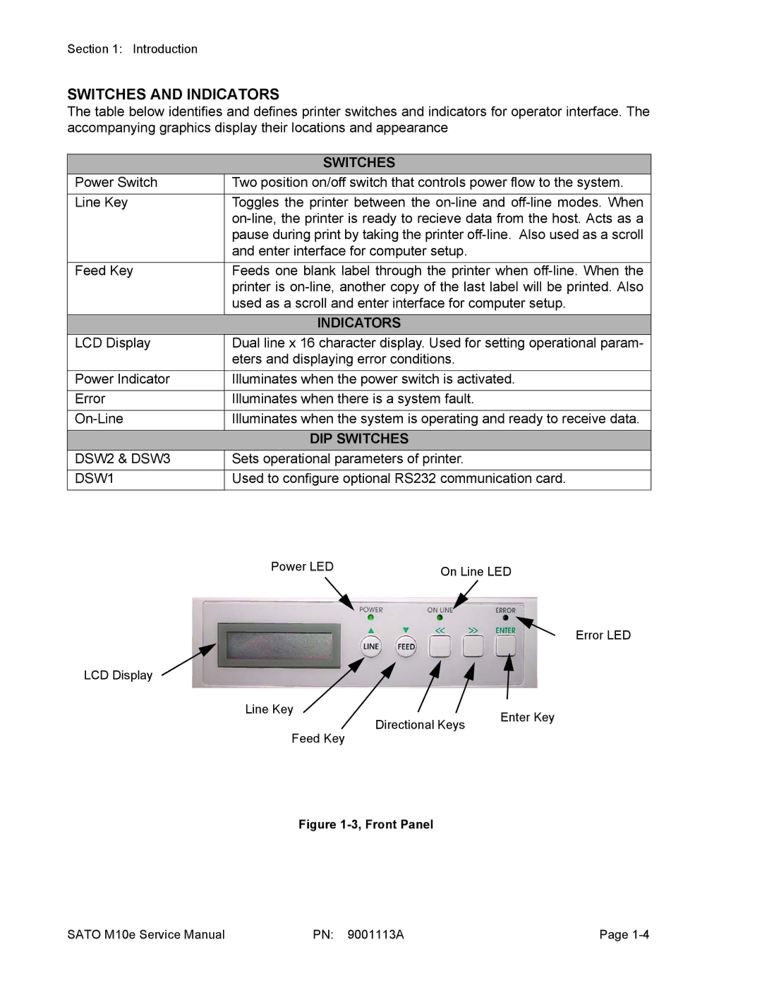
Indicators
Switches and Indicators
Switches
DIP Switches
Configuration Panel
Connection Ports
Connection Ports
Environmental
Physical Characteristics
Power
Print
Character Font Capabilities
Agfa Raster Fonts
Auto Smoothing Fonts
Vector Font
Downlaodable Fonts
BAR Code Capabilties
Regulatory Approvals
Interface Types
Receive Buffer
IEEE1284 Parallel Interface
Specifications
Init
Direction Signal Definition
RS232C Serial Interface Signals
RS232 Serial Interface
Host
Cable Requirements DB9
Printer
Universal Serial BUS USB Interface
Local Area Network LAN Optional Interface
ENQUIRE/ACK/NAK
Cancel can
BI-DIRECTIONAL Communications
Stream Identification
Print JOB
Accessories Installation
Label Cutter Installation
1b, Cutter Installation
Pcmcia Memory Expansion
REAL-TIME Clock
Insert clock chip 3 into the vacant IC Socket
Stacker KIT
Interface Module Upgrade
Media Unwind Unit
Accessories Installation PN 9001113A
RS232 TRANSMIT/RECEIVE Setting
DIP Switch Panels
OFF
DSW1-4
Printer SET UP
DSW2 OFF
DSW2-5
Setting DSW3
DSW3 OFF
Setting
Default Settings
Default Settings
Software Default Settings
Software Default Settings
Potentiometer Adjustments
LCD Panel Configuration
Configuration Modes
Normal Mode
Advanced Mode
LCD Display Definition
SET Calendar
Print Offset
Calendar
Card Mode
Sato Font Copy
Xxxxxxx Error
Card COPY/FORMAT
Copying
CARD-MEMORYCOPY
Program
Service Mode
Setting the threshold is
Auto Online Feed
Feed on Error
EYE XXV
Reprint W/FEED
Enable Disable
Priority Setting
Command LCD
EXT PIN 9 Select
Counters Mode
Test Print Mode
Default Settings Mode
MAINTENANCE/FACTORY Mode
ALL Clear Mode
Clear NON-STANDARD Protocol
Download User Defined Protocol Codes
HEX Dump Mode
QTY000000
Error Signals
Error LED LCD Message Beep Resolution Guide
Ribbon Wrinkling
Troubleshooting Table
Image Voids
Light Print Image
No Ribbon Movement
Power LED not Illuminated
Fuzzy Print Image
No Label Movement
Label LED is Illuminated
Error LED Illuminated
Will not Print When Data is Sent
Ribbon LED Illuminated
RS232 Serial Interface Troubleshooting
Universal Serial BUS USB Interface Troubleshooting
Parallel Interface Troubleshooting
LAN Ethernet Interface Troubleshooting
TCP/IP Troubleshooting
Netware Troubleshooting
Windows NT/LAN Server Troubleshooting
Windows 95/98 PEER-TO-PEER Troubleshooting
Diagnostic Label Printing
TP Test Module Usage
Dial Application Description
Ribbon Sensor Operation Verification
TP Test Module Usage
LCD Display Test Print Mode Configuration
Replacement Procedures
Print Head Replacement
Roller Belt Replacement
Roller Belt Replacement
Ribbon Belt Replacement
Platen Roller Replacement
Ribbon Belt Replacement
Platen Roller Replacement
Feed Roller Replacement
Feed Roller Replacement
Main Circuit Board Replacement
Interface Board Replacement
Circuit Board Replacement
Ribbon Drive Board Replacement
Interface Board Replacement
8b, Ribbon Drive Board Replacement
Memory Card Replacement
Panel Board Replacement
Power Supply Replacement
Panel Board Replacement
10, Power Board Replacement
Power Supply Fuse Replacement
11, Fuse Replacement
Circuit Board Fuse Replacement
12, Fuse Replacement
Drive Motor Replacement
13, Fuse Replacement
Ribbon Motor Replacement
14, Ribbon Motor Replacement
AUTO-LOAD Sensor Replacement
15, Auto-Load Sensor Replacement
LABEL-OUT Sensor Replacement
Label Position Sensor Replacement
16, Label Gap Sensor Replacement
17, Eye-Mark/Label-Out Sensor Replacement
Ribbon Sensor Replacement
Cutter Replacement
18, Ribbon Sensor Replacement
19, Cutter Assembly Replacement
Cutter Sensor Replacement
Eeprom Chip Replacement
20, Cutter Sensor Replacement
21, Eeprom Chip Replacement
Adjustment Procedures
Print Head Position
Print Head Alignment Adjustment
Print Head Alignment
Ribbon Wrinkle Adjustments
Ribbon Wrinkle Adjustments
Roller Belt Adjustment
Roller Belt Adjustment
Ribbon Belt Adjustment
Ribbon Belt Adjustment
Paper Guide Adjustment
Media Guide Adjustment
Pitch Sensor Adjustment
Place the DSW2-4 dip switch in the Off position
EYE-MARK Sensor Adjustment
Eye-Mark Sensor Adjustments
Label GAP Sensor Adjustment
Auto Load Sensor Adjustment
Label Gap Sensor Adjustment
10, Auto-Load Sensor Adjustment
Paper END Sensor Adjustment
11, Paper End Sensor Adjustment
Offset Label Stop Position Adjustment
LCD Display Adjustment
Print Darkness Adjustment
Adjustment Procedures PN 9001113A
Factory Resets
Factory Settings / Test Print
Clear Head Counters
Clear Cutter Counter
Press the Enter key to clear the cutter counter
Clear Eeprom
LCD Display Xxxxxall Clear Completed
Factory Resets PN 9001113A
Diagrams & Schematics
Housing Cover Removal & Installation
Media & Ribbon Loading
Media & Ribbon Loading
Block Diagram
Power Board
Printer
Printing Operational Sequence
Accessories & Sensors Location
Accessories & Sensors Location
Feed Direction
Print Reference Position