Section 7: Replacement Procedures
9 Route wiring harness as was removed and connect to the ribbon drive board.
NOTE: If unable to connect the motor wiring harness to the ribbon drive board with the main circuit board installed, remove the main circuit board in accordance with the Main Circuit Board Replacement procedures found in this section.
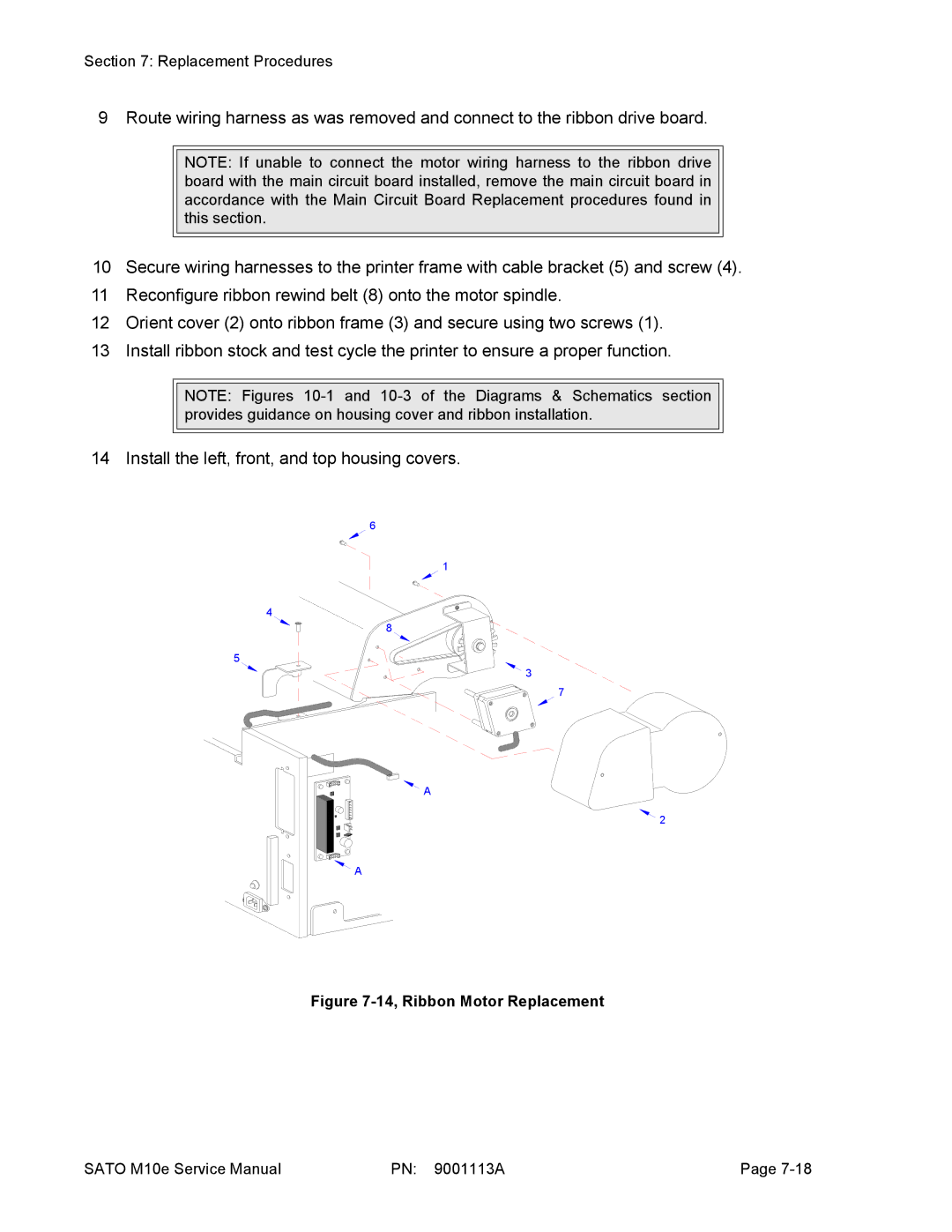
10Secure wiring harnesses to the printer frame with cable bracket (5) and screw (4).
11 Reconfigure ribbon rewind belt (8) onto the motor spindle.
12 Orient cover (2) onto ribbon frame (3) and secure using two screws (1). 13 Install ribbon stock and test cycle the printer to ensure a proper function.
NOTE: Figures
14 Install the left, front, and top housing covers.
6
1
4
8
5
3
7
![]() A
A
2
![]() A
A
Figure 7-14, Ribbon Motor Replacement
SATO M10e Service Manual | PN: 9001113A | Page |
