Section 8: Adjustment Procedures
4 Loosen two set screws (not shown) through driver ports (2) of ribbon cover (1).
NOTE: The driver ports of the ribbon cover are aligned with those of the top frame. Insert a long driver through the driver ports of the ribbon cover and top frame to the set screw of each port.
5 Turn adjustment axle (3) while watching the movement of the print head on the platen roller.
NOTE: There are two orifices midway in the axle. Insert something of sufficient strength into one of the orifices to use as leverage when turning. There is also a scale on one end of the axle to assist in incremental adjustment.
6 When properly positioned, retighten the set screws.
PRINT HEAD ALIGNMENT
Course print head alignment is acheived by loosening the set screw on the left end of the mounting assembly and manually adjusting the print head forward or backward as deemed necessary. This can only be acheived while the printer is off and with the print head open. Course adjustment should only be required if the print position is grossly out of adjustment.
Fine adjustment is achieved by leaving the left set screw secure and loosening the right set screw. The mounting assembly is designed to allow the print head to eccentrically oscilate when the right set screw is loosened and the adjustment screw is turned. The adjustment screw is directly connected to an eccentric cam and provides print head motion. The following procedure provides instruction on fine adjustment of print head alignment.
1Set the printer to continuously print test labels and allow several labels to print.
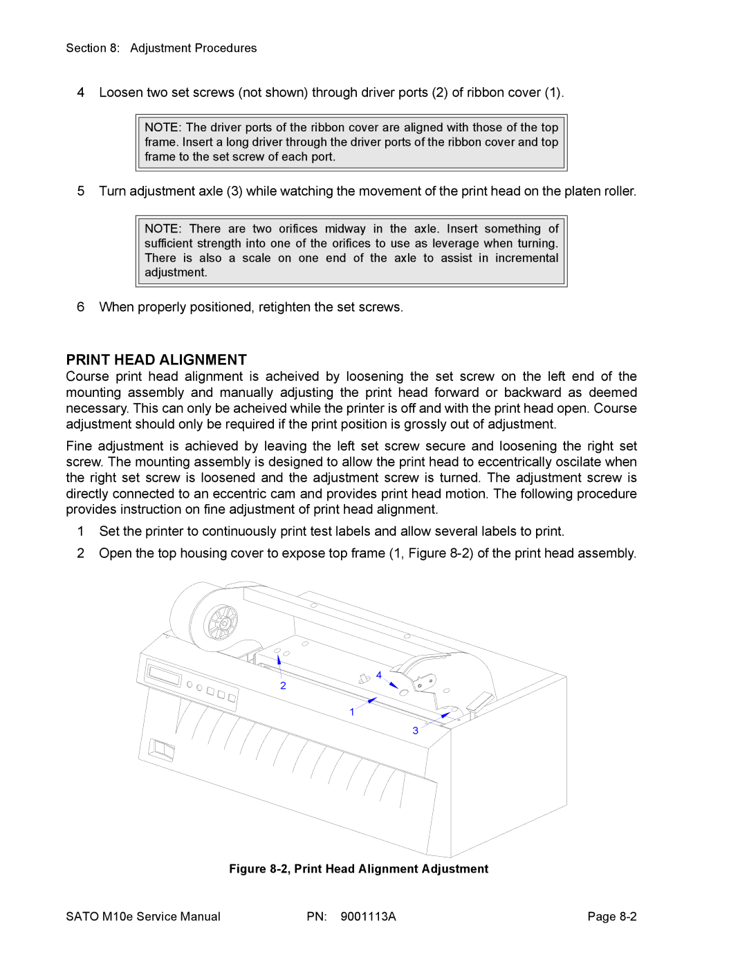
2Open the top housing cover to expose top frame (1, Figure
4
2
1
3
Figure 8-2, Print Head Alignment Adjustment
SATO M10e Service Manual | PN: 9001113A | Page |