Section 7: Replacement Procedures
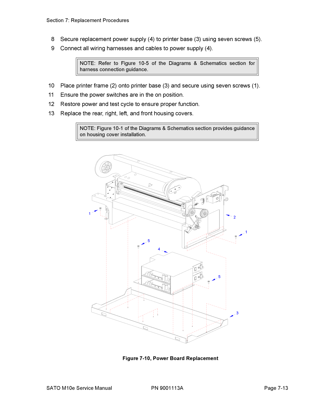
8Secure replacement power supply (4) to printer base (3) using seven screws (5).
9Connect all wiring harnesses and cables to power supply (4).
NOTE: Refer to Figure
10Place printer frame (2) onto printer base (3) and secure using seven screws (1).
11Ensure the power switches are in the on position.
12Restore power and test cycle to ensure proper function.
13Replace the rear, right, left, and front housing covers.
NOTE: Figure
1 ![]()
![]() 2
2
1
5
4
5
3
Figure 7-10, Power Board Replacement
SATO M10e Service Manual | PN 9001113A | Page |