Section 7: Replacement Procedures
7Test cycle to ensure a proper function.
8Install the right, front, and top housing covers.
NOTE: Figure
2
3 | 1 |
A
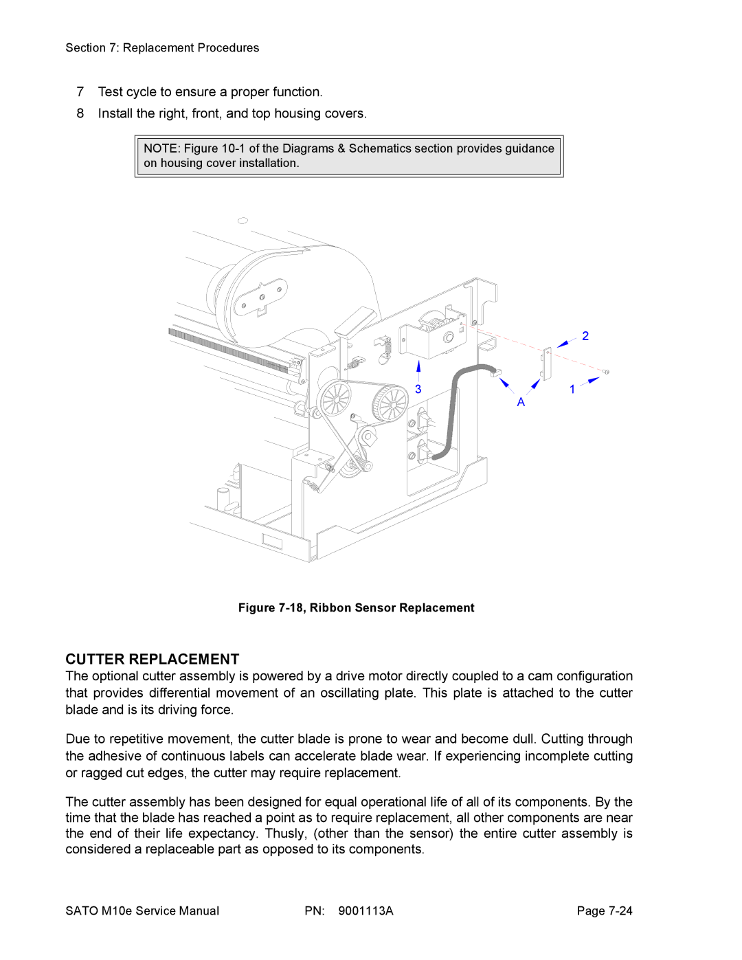
Figure 7-18, Ribbon Sensor Replacement
CUTTER REPLACEMENT
The optional cutter assembly is powered by a drive motor directly coupled to a cam configuration that provides differential movement of an oscillating plate. This plate is attached to the cutter blade and is its driving force.
Due to repetitive movement, the cutter blade is prone to wear and become dull. Cutting through the adhesive of continuous labels can accelerate blade wear. If experiencing incomplete cutting or ragged cut edges, the cutter may require replacement.
The cutter assembly has been designed for equal operational life of all of its components. By the time that the blade has reached a point as to require replacement, all other components are near the end of their life expectancy. Thusly, (other than the sensor) the entire cutter assembly is considered a replaceable part as opposed to its components.
SATO M10e Service Manual | PN: 9001113A | Page |