Section 8: Adjustment Procedures
PAPER END SENSOR ADJUSTMENT
This adjustment will require the use of a multimeter and the TP Test Module.
NOTE: Figure
1 Remove the top, front, and left housing cover to access main circuit board (1, Figure
NOTE: Figure
2 Turn VR8 potentiometer (2) fully
![]()
![]() NOTE: An audible click should be heard.
NOTE: An audible click should be heard.
3 Connect test module (3) to main circuit board connector (4).
NOTE: Refer to TP Test Module Usage in the TRoubleshooting section for additional instruction on test module usage.
5![]()
3 ![]()
|
|
| 1A |
|
|
|
| 2A | 6 |
|
|
| 3A | |
| 0 |
| 4A |
|
| 1 | 5A |
| |
8 |
|
| ||
|
|
| ||
|
| 6A |
| |
|
|
|
| |
7 |
| 2 | 1B |
|
|
|
|
| |
|
|
| 2B |
|
6 |
| 3 | 3B |
|
4 |
|
|
| |
5 |
| 4B |
| |
| D SIG |
| 5B |
|
GN |
| 6B |
| |
|
|
|
| |
2
7
IEEE1284+ RSBOARD
4
1
|
| 1A |
|
| 2A |
|
| 3A |
0 |
| 4A |
1 | 5A | |
8 |
| |
| 6A | |
7 | 2 | 1B |
|
| |
|
| 2B |
6 | 3 | 3B |
|
| |
5 | 4 | 4B |
GND | SIG | 5B |
| 6B | |
3 |
| |
|
|
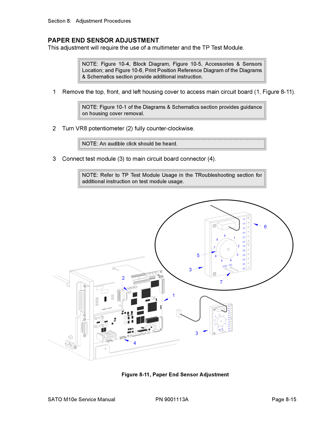
Figure 8-11, Paper End Sensor Adjustment
SATO M10e Service Manual | PN 9001113A | Page |