Section 7: Replacement Procedures
15Secure interface board (3) to printer housing using two screws (2).
16Reconnect all wiring harnesses to main circuit board (1).
NOTE: Refer to Figure
17Reconnect power supply cord, confirm correct potentiometer settings, and perform Factory Reset.
18Test cycle, and reattach housing covers.
NOTE: Figure
7
3
8
1
2 | 4 |
| 5 |
6
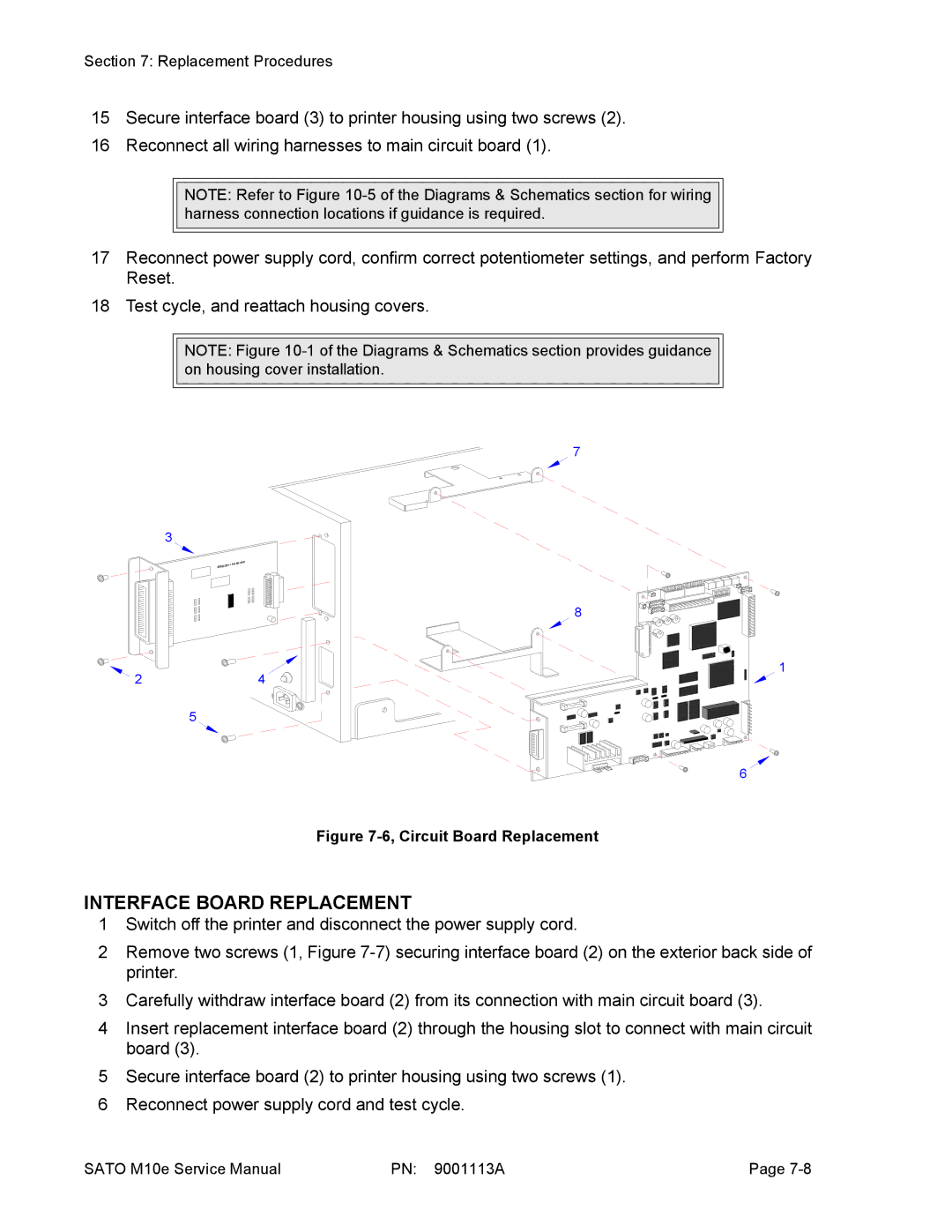
Figure 7-6, Circuit Board Replacement
INTERFACE BOARD REPLACEMENT
1Switch off the printer and disconnect the power supply cord.
2Remove two screws (1, Figure
3Carefully withdraw interface board (2) from its connection with main circuit board (3).
4Insert replacement interface board (2) through the housing slot to connect with main circuit board (3).
5Secure interface board (2) to printer housing using two screws (1).
6Reconnect power supply cord and test cycle.
SATO M10e Service Manual | PN: 9001113A | Page |