Section 6: Troubleshooting
|
|
|
|
|
|
| 1A |
|
|
|
|
|
|
| 2A |
|
|
|
|
|
|
| 3A |
|
|
|
|
| 0 |
| 4A |
|
|
|
|
| 1 | 5A | |
|
| 8 |
|
|
| ||
|
|
|
|
|
| ||
|
|
|
|
|
| 6A | |
|
|
|
|
|
|
| |
|
| 7 |
|
|
| 2 | 1B |
|
|
|
|
|
|
| |
| 5 | 6 |
|
|
|
| 2B |
|
|
|
| 3 | 3B | ||
|
|
|
|
| 5 | 4 | 4B |
|
|
|
|
|
| ||
|
|
|
|
| D SIG | 5B | |
|
|
|
|
|
| ||
| 1 |
|
|
| GN |
| 6B |
|
|
|
|
|
| ||
|
|
|
| 3 | 4 |
| |
| RD |
|
|
|
| 1A |
|
|
|
|
|
| 2A |
| |
IEEE1284 | +RS BOA |
|
|
|
|
| |
|
|
|
|
|
| 3A |
|
|
|
| 0 |
|
| 4A |
|
|
| 8 |
| 1 | 5A |
| |
|
|
|
|
| 6A |
| |
|
|
|
|
|
|
| |
|
| 7 |
|
| 2 | 1B |
|
|
|
|
|
|
|
| |
|
|
|
|
|
| 2B |
|
|
| 6 |
|
| 3 | 3B |
|
|
| 5 |
|
| 4 | 4B |
|
|
| GND | SIG | 5B |
| ||
| 1 |
| 6B |
| |||
|
|
|
|
|
| ||
|
|
|
|
|
|
| |
![]() 2
2
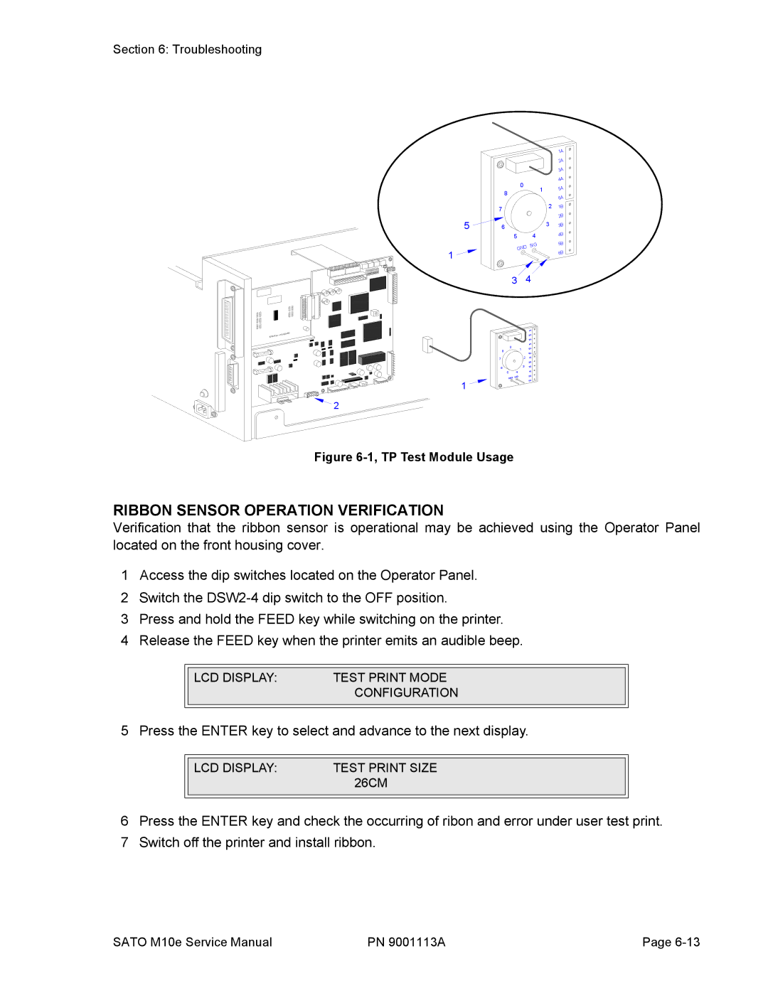
Figure 6-1, TP Test Module Usage
RIBBON SENSOR OPERATION VERIFICATION
Verification that the ribbon sensor is operational may be achieved using the Operator Panel located on the front housing cover.
1Access the dip switches located on the Operator Panel.
2Switch the
3Press and hold the FEED key while switching on the printer.
4Release the FEED key when the printer emits an audible beep.
|
|
|
|
| LCD DISPLAY: | TEST PRINT MODE |
|
|
| CONFIGURATION |
|
|
|
|
|
5 Press the ENTER key to select and advance to the next display.
|
|
|
|
| LCD DISPLAY: | TEST PRINT SIZE |
|
|
| 26CM |
|
|
|
|
|
6Press the ENTER key and check the occurring of ribon and error under user test print.
7Switch off the printer and install ribbon.
SATO M10e Service Manual | PN 9001113A | Page |
