Section 7: Replacement Procedures
NOTE: Figure
3Remove two screws (2) securing interface board (3) on the exterior back side of printer.
4Carefully withdraw interface board (3) from its connection with main circuit board (1).
5Remove optional memory card (4) from the exterior back side of printer.
6Mark, tag, and disconnect all wiring harnesses from main circuit board (1).
7Remove two screws (5) securing main circuit board (1) to exterior back side of printer.
8Remove four screws (6) securing main circuit board (1) to mounting brackets (7) and (8).
9Manipulate main circuit board (1) from printer frame.
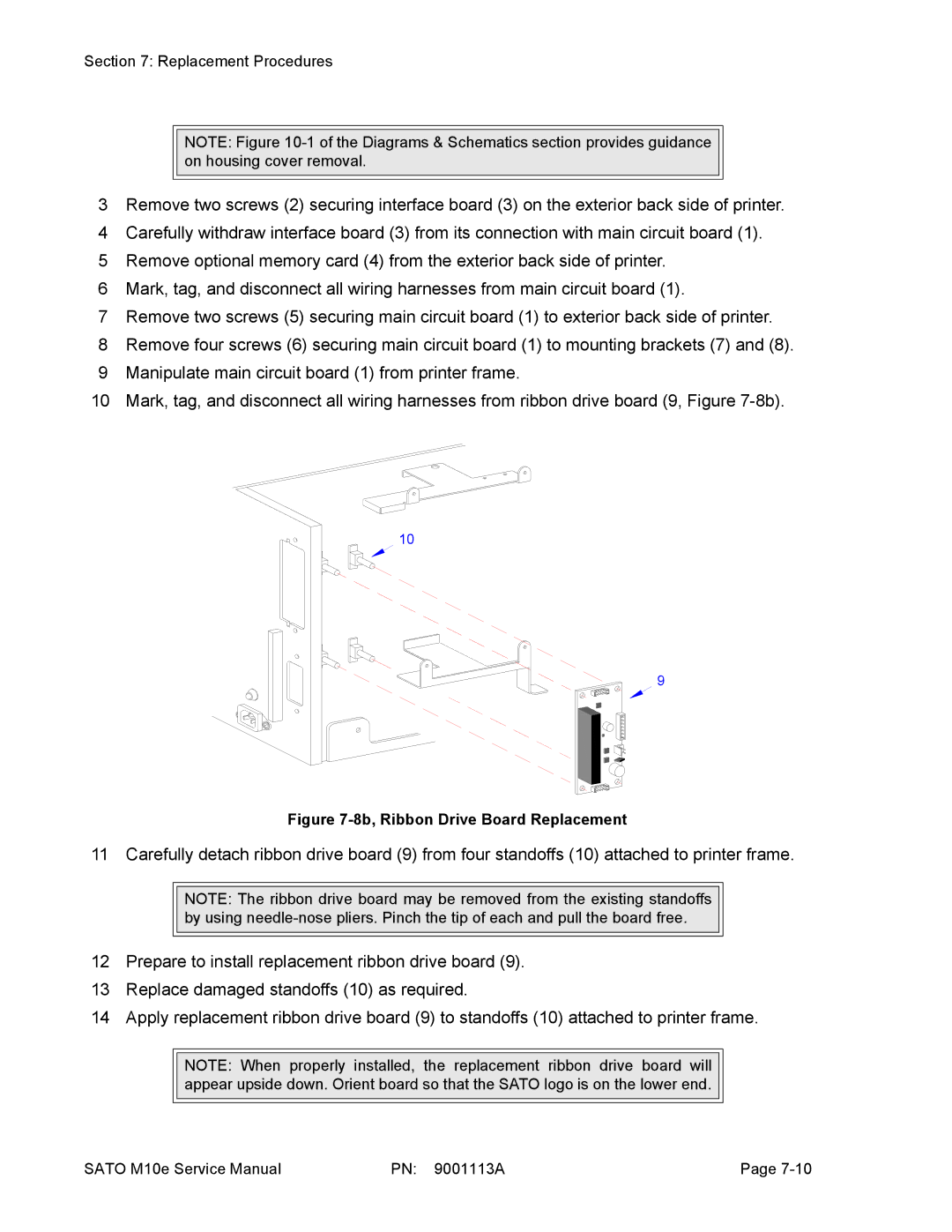
10 Mark, tag, and disconnect all wiring harnesses from ribbon drive board (9, Figure
10
9
Figure 7-8b, Ribbon Drive Board Replacement
11 Carefully detach ribbon drive board (9) from four standoffs (10) attached to printer frame.
NOTE: The ribbon drive board may be removed from the existing standoffs by using
12Prepare to install replacement ribbon drive board (9).
13Replace damaged standoffs (10) as required.
14Apply replacement ribbon drive board (9) to standoffs (10) attached to printer frame.
NOTE: When properly installed, the replacement ribbon drive board will appear upside down. Orient board so that the SATO logo is on the lower end.
SATO M10e Service Manual | PN: 9001113A | Page |