Section 7: Replacement Procedures
8 Install the left, front, and top housing covers.
NOTE: Figure
9 Restore power and test cycle to ensure proper function.
1
B
A
C
2
D
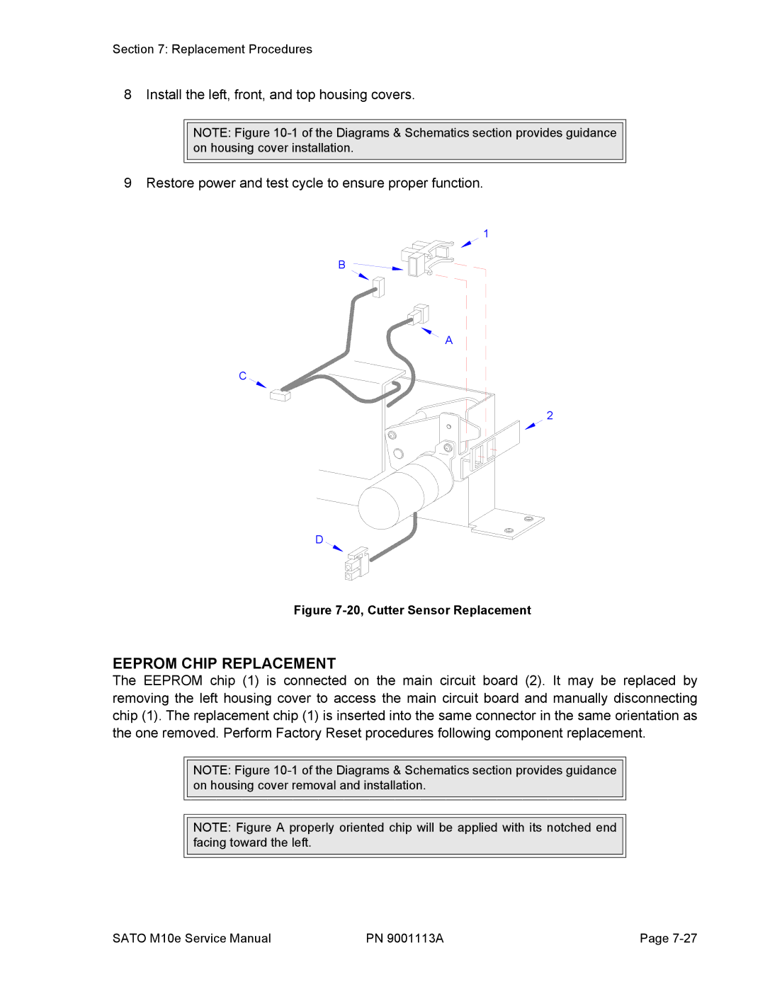
Figure 7-20, Cutter Sensor Replacement
EEPROM CHIP REPLACEMENT
The EEPROM chip (1) is connected on the main circuit board (2). It may be replaced by removing the left housing cover to access the main circuit board and manually disconnecting chip (1). The replacement chip (1) is inserted into the same connector in the same orientation as the one removed. Perform Factory Reset procedures following component replacement.
NOTE: Figure
NOTE: Figure A properly oriented chip will be applied with its notched end facing toward the left.
SATO M10e Service Manual | PN 9001113A | Page |