Section 7: Replacement Procedures
1Switch off the printer and disconnect the power supply cord.
2Remove top, front, left, and right housing covers to access cutter assembly (1, Figure
NOTE: Figure
3Disconnect all relative wiring harnesses.
4Remove three screws (2) securing cutter assembly (1) to the printer frame.
5Remove three screws (3) securing rear cover (4) to cutter assembly (1).
6Remove four screws (5) securing front cover (6) to cutter assembly (1).
7Apply front cover (6) to replacement cutter assembly (1) and secure using four screws (5).
8Apply rear cover (5) to replacement cutter assembly (1) and secure using three screws (3).
9Position replacement cutter assembly (1) onto the printer frame as design dictates and secure using three screws (2).
1
2
5
6 ![]()
4
3
1
2
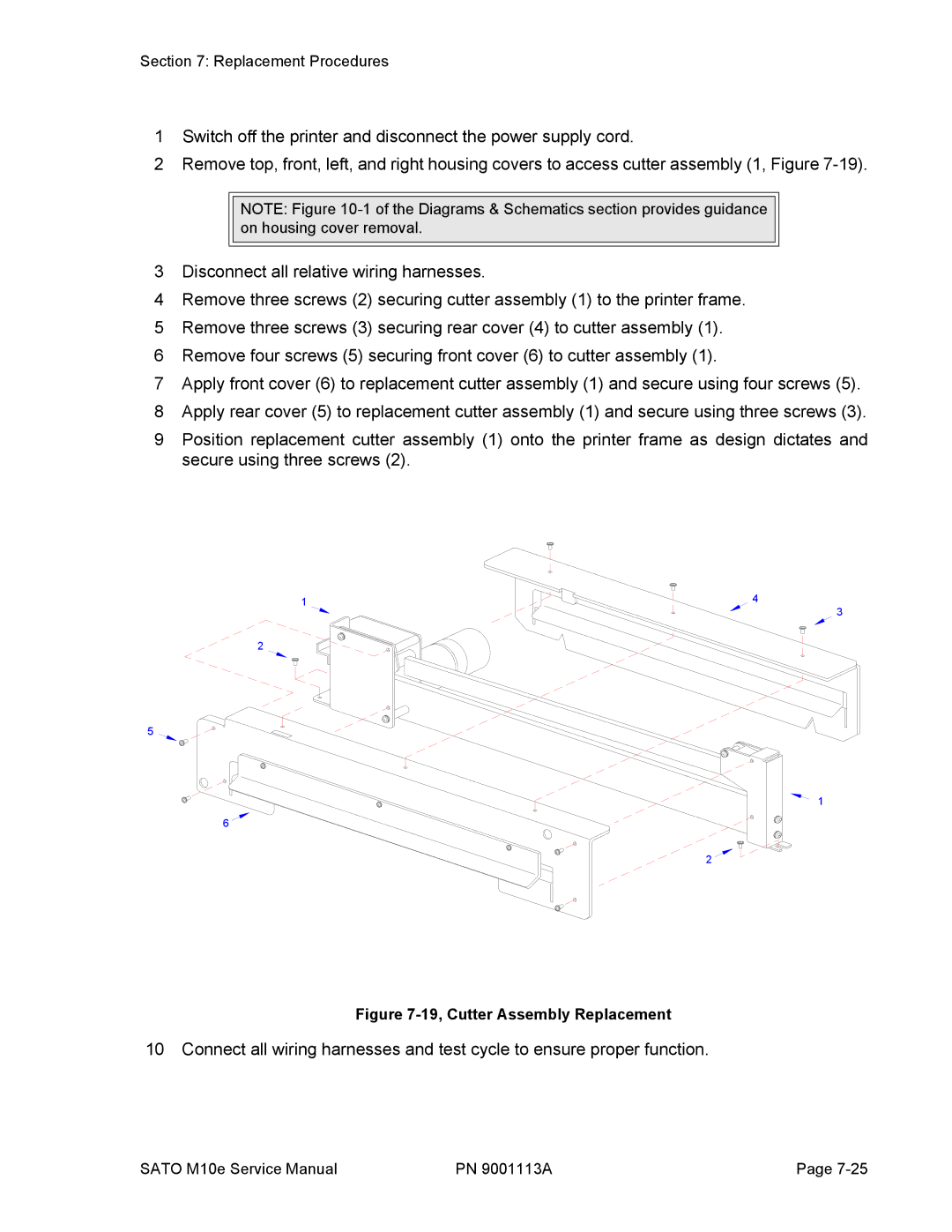
Figure 7-19, Cutter Assembly Replacement
10 Connect all wiring harnesses and test cycle to ensure proper function.
SATO M10e Service Manual | PN 9001113A | Page |