Section 7: Replacement Procedures
CIRCUIT BOARD FUSE REPLACEMENT
The M10e Printer has four fuses; two are wired to the power supply while the other two are directly connected to the main circuit board.
1Switch off the printer and disconnect the power supply cord.
2Remove the top, front, and left housing covers to expose fuses (1, Figure
NOTE: Figure
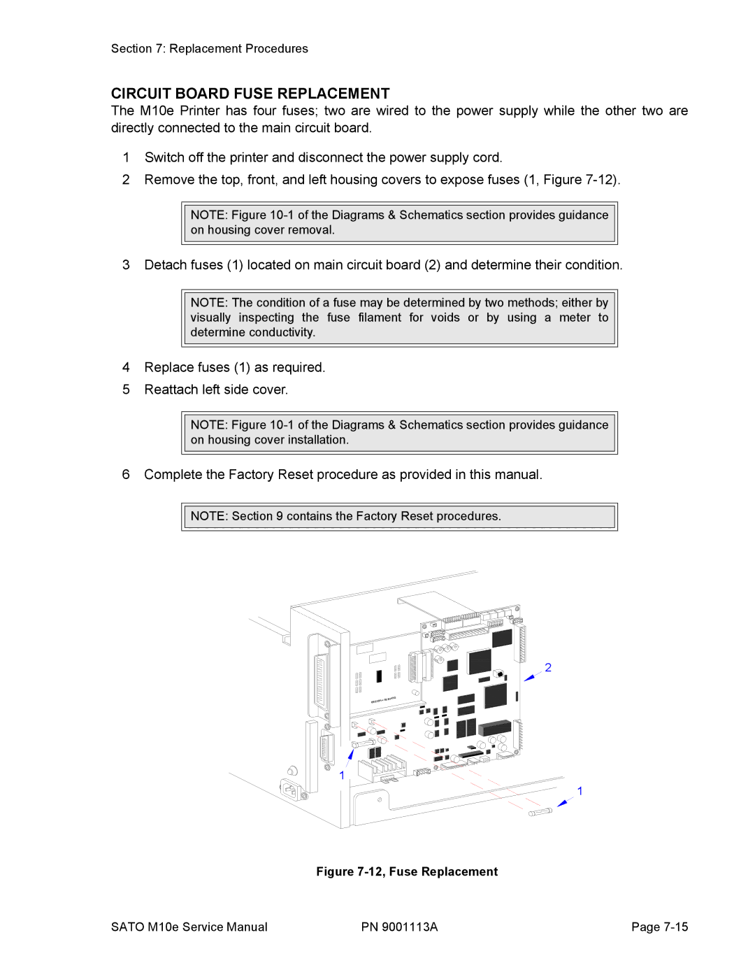
3 Detach fuses (1) located on main circuit board (2) and determine their condition.
NOTE: The condition of a fuse may be determined by two methods; either by visually inspecting the fuse filament for voids or by using a meter to determine conductivity.
4Replace fuses (1) as required.
5Reattach left side cover.
NOTE: Figure
6 Complete the Factory Reset procedure as provided in this manual.
![]()
![]() NOTE: Section 9 contains the Factory Reset procedures.
NOTE: Section 9 contains the Factory Reset procedures.
2
84+ RS | BOARD |
IEEE12 |
|
1
1
Figure 7-12, Fuse Replacement
SATO M10e Service Manual | PN 9001113A | Page |