Section 7: Replacement Procedures
NOTE: Figure
3 |
|
A | A |
| 1 |
4 | B |
B | C | |
2 | ||
| ||
| C |
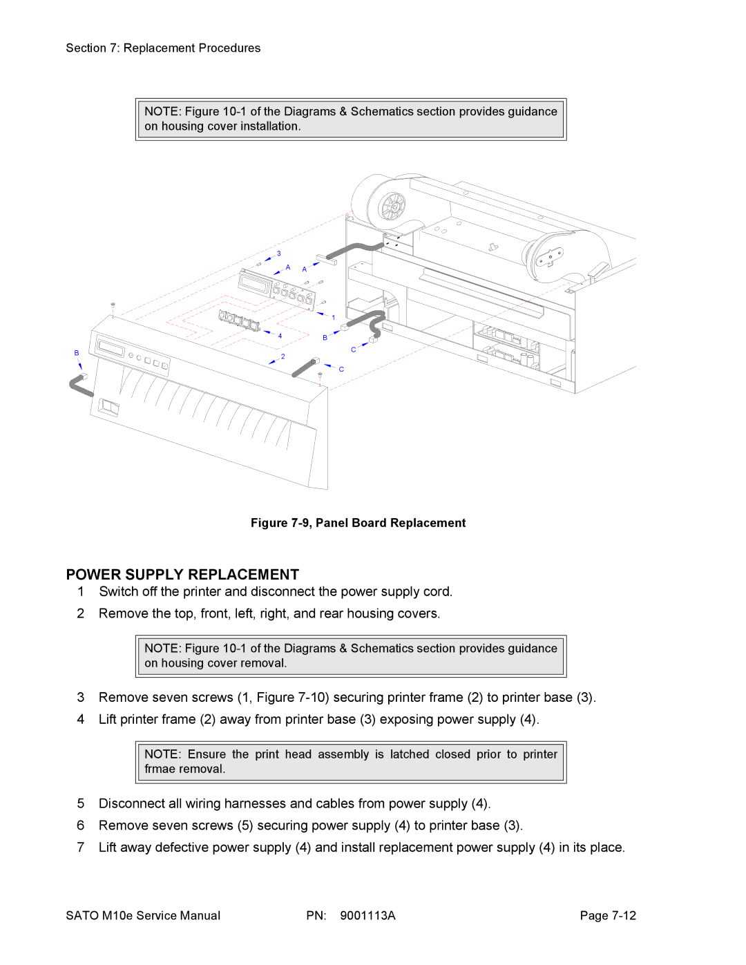
Figure 7-9, Panel Board Replacement
POWER SUPPLY REPLACEMENT
1Switch off the printer and disconnect the power supply cord.
2Remove the top, front, left, right, and rear housing covers.
NOTE: Figure
3Remove seven screws (1, Figure
4Lift printer frame (2) away from printer base (3) exposing power supply (4).
NOTE: Ensure the print head assembly is latched closed prior to printer frmae removal.
5Disconnect all wiring harnesses and cables from power supply (4).
6Remove seven screws (5) securing power supply (4) to printer base (3).
7Lift away defective power supply (4) and install replacement power supply (4) in its place.
SATO M10e Service Manual | PN: 9001113A | Page |