Section 4: Accessories Installation
4Lift away
5Place cutter assembly (4, Figure
NOTE: When properly placed, the cutter motor should be oriented on the left side of the printer and protrude behind the main circuit board.
6 Secure cutter assembly (4) to printer frame (3) using three screws (5).
NOTE: The cutter will be secured with two screws applied to the left end, and one screw to the right. They will be appied in different orifices on the printer frame than the dispenser.
7 Apply safety switch (6) to front housing cover (7) and secure using screw (8).
NOTE: When properly applied, the safety switch will be mounted to the interior surface of the front housing cover oriented so that its mounting orifices are aligned with the orifice in the cover and the mounting pin. The switch will remain in the open position when mounted.
| 3 |
B | A |
| 5 |
C |
|
8 | C |
6 | 4 |
|
5
![]() 7
7
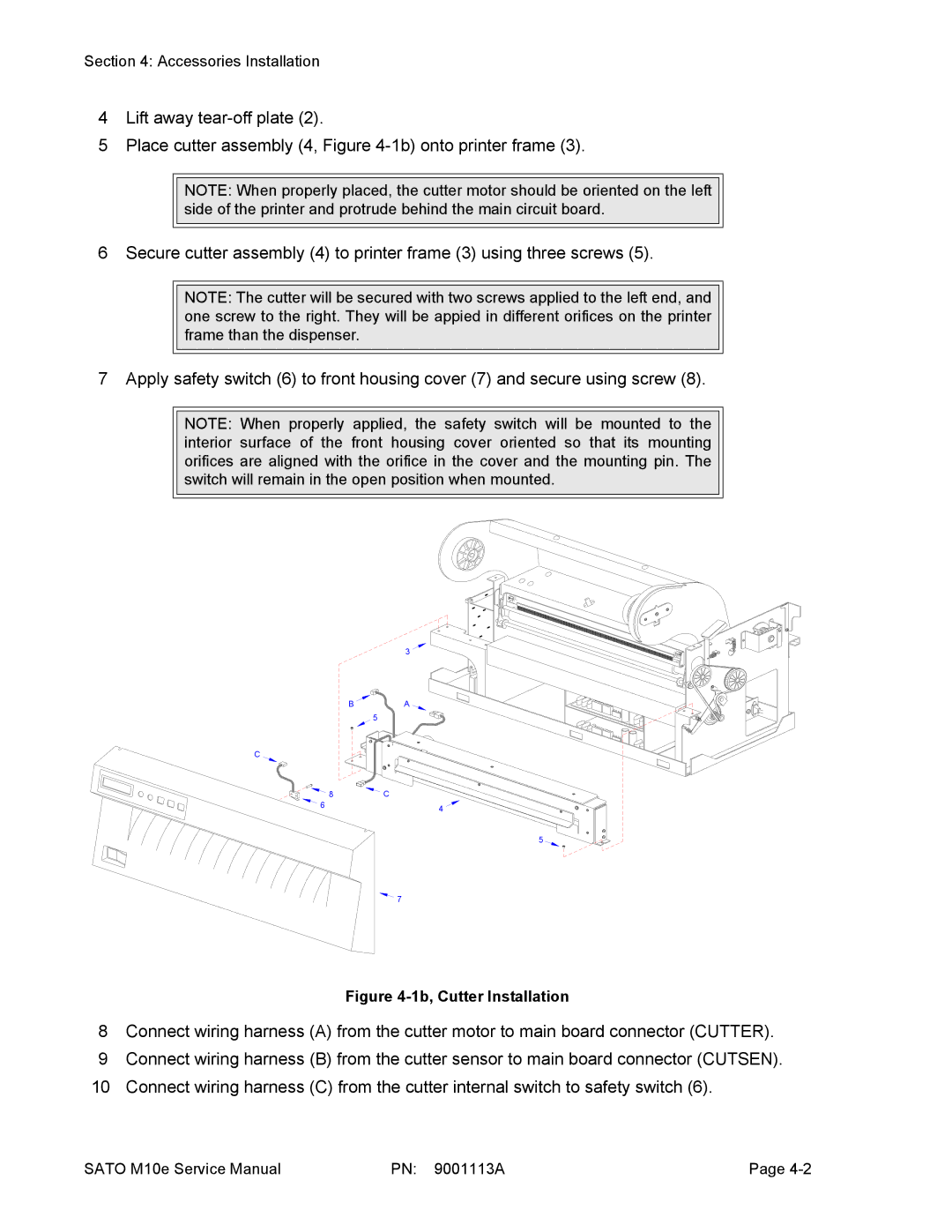
Figure 4-1b, Cutter Installation
8Connect wiring harness (A) from the cutter motor to main board connector (CUTTER).
9Connect wiring harness (B) from the cutter sensor to main board connector (CUTSEN).
10 Connect wiring harness (C) from the cutter internal switch to safety switch (6).
SATO M10e Service Manual | PN: 9001113A | Page |